Socket and connector using socket

A technology of sockets and plugs, which is applied in the direction of connection, parts of connection devices, contact parts, etc., can solve the problems of reduced number of contact pressure, deterioration of tactile feeling, socket and plug, and weakened fitting force of socket and plug.

Active Publication Date: 2014-04-30
PANASONIC INTELLECTUAL PROPERTY MANAGEMENT CO LTD
View PDF10 Cites 18 Cited by
  • Summary
  • Abstract
  • Description
  • Claims
  • Application Information

AI Technical Summary

Problems solved by technology

However, if the connector is to be miniaturized and thinned, there is a possibility that the tactile feeling when the socket and the header are mated may be deteriorated, or the fitting of the socket and the header may be easily released.
This is because, with the miniaturization and thinning of the connector, the number of socket-side terminals and header-side terminals will decrease or the contact pressure between these terminals will decrease, resulting in a weakened fitting force between the socket and the header.

Method used


Image

  • Socket and connector using socket
  • Socket and connector using socket
  • Socket and connector using socket

Examples


Embodiment Construction

[0035] Hereinafter, embodiments of the present invention will be described in detail with reference to the drawings.

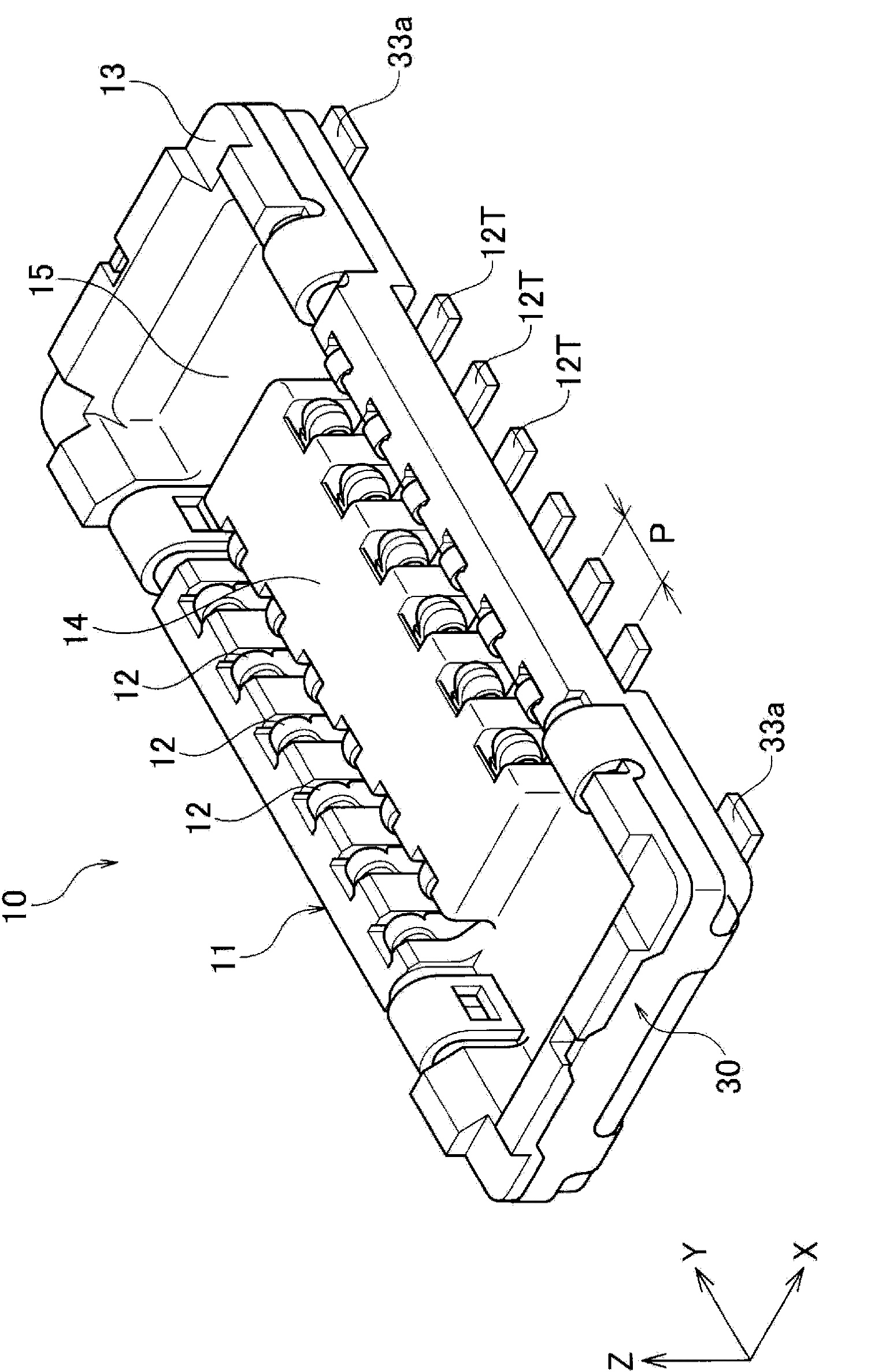
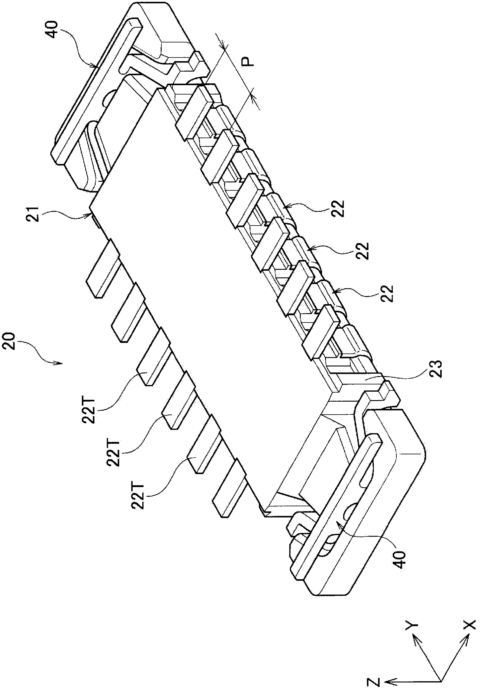
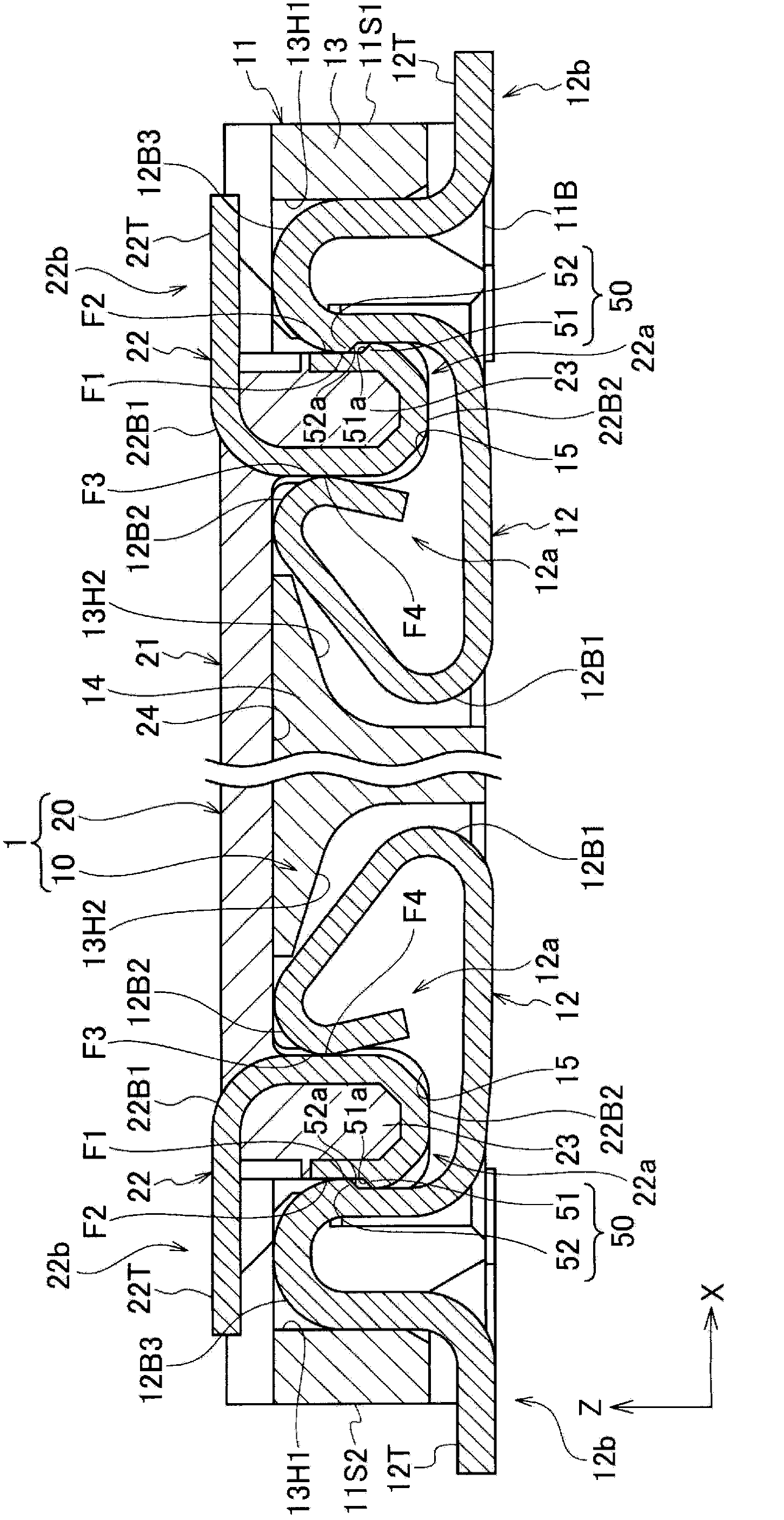
[0036] Figure 1 to Figure 7 It is a figure showing one embodiment of the connector 1 related to the present invention, such as image 3 As shown, the connector 1 of this embodiment includes a socket 10 and a header 20 that are fitted into each other. It should be noted that, when describing this embodiment, the X direction in the figure is taken as the width direction of the connector 1 (socket housing 11, header housing 21), the Y direction is taken as the length direction, and the Z direction is taken as the The up and down direction will be explained.

[0037] Such as figure 1 As shown, the socket 10 includes a socket case (socket main body) 11 molded from an insulating synthetic resin to form a rectangular (rectangular) shape as a whole in plan view. In the socket housing 11 , a plurality of contacts (socket-side terminals) 12 are arranged at a predet...


PUM


Abstract

The invention provides a socket and a connector using the socket. A header-side holding bracket (40) is provided with latches (42) which can move relative to the connection section (base section) (41) of the header-side holding bracket (40) in the width direction (X) of the connector (1) (header housing (21)). A socket-side holding bracket (30) has formed therein catch holes (catch sections) (37) capable of engaging with the latches (42).

Description

technical field [0001] The present invention relates to a socket and a connector using the socket. Background technique [0002] Conventionally, a connector has been used that includes: a socket in which a plurality of socket-side terminals and socket-side holding fittings are arranged on a socket body; a plurality of header-side terminals and The header side holds the header of the accessory (for example, refer to Patent Document 1). [0003] In this patent document 1, the conductor patterns of the circuit board connected to the respective terminals are electrically connected to each other by fitting the socket and the header together to bring corresponding terminals into contact with each other. [0004] prior art literature [0005] patent documents [0006] Patent Document 1: Japanese Patent Laid-Open No. 2008-270099 [0007] Summary of the invention [0008] The problem to be solved by the invention [0009] However, in the recent connector technology, along with ...

Claims


Application Information

Patent Timeline
Patent Type & Authority Applications(China)
IPC IPC(8): H01R13/631H01R12/71
CPCH01R12/716H01R13/20H01R12/71H01R12/73H01R13/6278H01R13/631H01R13/639H01R13/6275H01R13/6271
Inventor 田中友规宫崎洋二
Owner PANASONIC INTELLECTUAL PROPERTY MANAGEMENT CO LTD
Why Eureka
Try Eureka