Selection of radiation shaping filter

A technology for filtering and selecting radiation, applied in the field of X-ray imaging systems, which can solve problems such as troublesome and hinder the simplification of the operation of X-ray imaging systems.

Active Publication Date: 2014-05-07
SIEMENS HEATHCARE GMBH
View PDF8 Cites 16 Cited by
  • Summary
  • Abstract
  • Description
  • Claims
  • Application Information

AI Technical Summary

Problems solved by technology

This may not always guarantee the best choice for a radiation shape filter
Furthermore, the assignment of radiation selecti

Method used


Image

  • Selection of radiation shaping filter
  • Selection of radiation shaping filter

Examples


Embodiment Construction

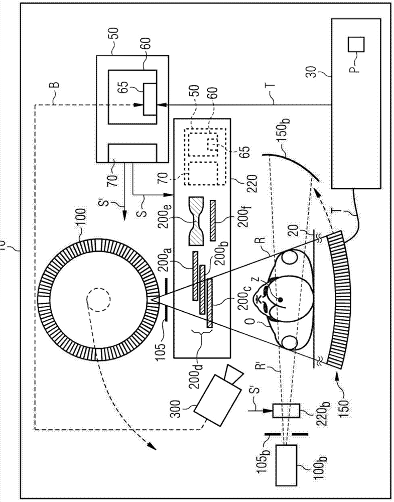
[0049] figure 1 A cross-sectional representation perpendicular to the system axis z of an x-ray imaging system, here a CT system 10 for generating two-dimensional, three-dimensional or multidimensional computed tomography image data is schematically shown. The CT system 10 here essentially consists of a conventional scanner in which an x-ray detector 150 on a gantry and an x-ray source 100 arranged opposite the detector 150 rotate around the measurement volume together. This is shown schematically by dashed lines with arrows. In front of the scanner is a patient support or patient table 20, the upper part of which, together with the examination object O or patient O located thereon, is movable relative to the scanner in the direction of the system axis z in order to move the patient O relative to the detector 150 Move through the measurement space. System axis z simultaneously forms a common axis of rotation for detector 150 and x-ray source 100 . The scanner and the patien...


PUM


Abstract

A method for selecting a radiation shaping filter is disclosed, which modifies the spatial distribution of the intensity and/or the spectrum of x-rays of an x-ray source of an imaging system. In an embodiment, anatomical measurement data of an object under examination is recorded, from which with the aid of the imaging system image data is creatable. The radiation shaping filter is selected automatically on the basis of the recorded anatomical measurement data of the object under examination. An imaging system, in which a radiation shaping filter is selected, is further disclosed.

Description

technical field [0001] The invention relates to a method for selecting a radiation shape filter, a method for controlling a radiation shape filter arrangement, a method for controlling the spectrum of an x-ray source, a method for controlling an x-ray imaging system The method and an X-ray imaging system with a radiation shape filter device. Background technique [0002] In X-ray imaging systems, especially in computed tomography systems, a diaphragm is usually installed between the X-ray source and the examination object, which initially determines the opening angle of the X-ray radiation beam and The shape of the area. A radiation shape filter is often arranged downstream of this aperture in the radiation path of the x-ray radiation, which can additionally change the intensity of the x-ray radiation spatially or also spectrally. This is an essentially flat filter which transmits the total (typically limited by an aperture) x-rays, without the filter needing to have openi...

Claims


Application Information

Patent Timeline
IPC IPC(8): A61B6/00A61B6/03
CPCA61B6/035A61B6/03A61B6/06A61B6/545A61B6/40A61B6/0457A61B6/4035A61B6/542A61B6/4435A61B6/032A61B6/482G21K1/10A61B6/544A61B6/08A61B6/0492A61B6/0487
Inventor H-C.贝克尔T.弗洛尔B.施米特
Owner SIEMENS HEATHCARE GMBH
Why Eureka
Try Eureka