Method for manufacturing carrier tape

A manufacturing method and carrier tape technology, applied in packaging, etc., can solve the problem of reduced operability and achieve the effect of improving operability

Inactive Publication Date: 2014-05-07
MURATA MFG CO LTD
View PDF7 Cites 11 Cited by
  • Summary
  • Abstract
  • Description
  • Claims
  • Application Information

AI Technical Summary

Problems solved by technology

Therefore, there is a possibility that the op

Method used


Image

  • Method for manufacturing carrier tape
  • Method for manufacturing carrier tape
  • Method for manufacturing carrier tape

Examples


Example Embodiment

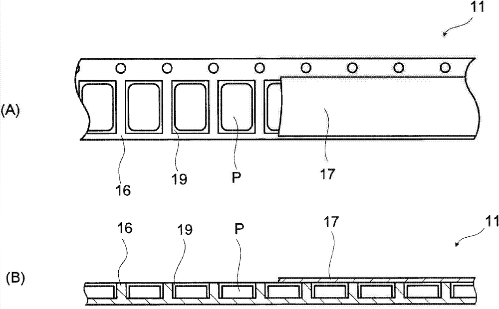
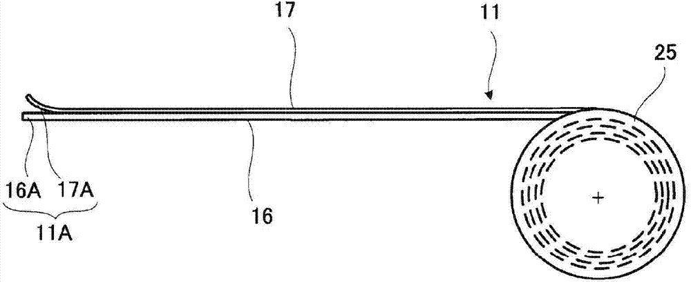
[0049] Such as figure 1 (A) and figure 1 As shown in (B), the carrier tape 11 is composed of a tape main body 16, a cover film 17, and a plurality of electronic components P. The belt main body 16 is a long body, and a plurality of recesses 19 are formed at predetermined intervals in the longitudinal direction. The electronic component P is housed in each of the plurality of recesses 19. A cover film 17 is attached to the tape main body 16 to prevent the stored electronic components P from flying out.

[0050] Here, the electronic component P is, for example, a laminated ceramic capacitor having a vertical length of 2.0 mm, a horizontal length of 1.25 mm, and a height of 0.6 mm. The size of the tape main body 16 of the carrier tape 11 is, for example, a thickness of 1 mm, a width of 8 mm, and a length of 17 mm, and the pitch of the recesses 19 formed at predetermined intervals is, for example, 4 mm. The material of the belt main body 16 is paper or resin. The size of the cov...


PUM


Abstract

A method for manufacturing a carrier tape is disclosed. With the method, a carrier tape which can store more electronic components and is excellent in operability in the installation process is manufactured. A non-storage part (18A) which does not store electronic components (P) is arranged at the position of an end part (11A) of a carrier tape (11). At the non-storage part (18A), a film non-adhesive part (28A) is formed on a tape main body (16). The tape main body (16) and a cover film (17) are cut off at the film non-adhesive part (28A). As the electronic components (P) can be stored on the carrier tape (11) without cutting off the tape main body (16), the number of stored electronic components (P) is increased. In addition, by forming a rolling part (17A), the cover film (17) can be easily peeled off.

Description

technical field [0001] The invention relates to a method for manufacturing a carrier tape used for storing electronic components. Background technique [0002] The carrier tape is composed of a tape main body, an electronic component, and a cover film, wherein the above-mentioned tape main body has a plurality of recesses, and the above-mentioned electronic component is accommodated in each of the plurality of recesses, and the above-mentioned cover film is adhered to the tape main body, so that The opening sides of the plurality of recesses are blocked. In recent years, attention to environmental problems has increased, and the above-mentioned carrier tapes are also required to take the environment into consideration. [0003] Figure 9 It is a schematic diagram of end portion 111A of carrier tape 111 described in Patent Document 1 (Japanese Patent Application Laid-Open No. 9-142567 ) viewed from the front. Such as Figure 9 As shown, before reaching the end 111A of the c...

Claims


Application Information

Patent Timeline
IPC IPC(8): B65D73/02B65D85/86
Inventor 福田谦一
Owner MURATA MFG CO LTD
Why Eureka
Try Eureka