Cross beam and stand column connecting structure

A technology for connecting structures and beams, used in building structures, buildings, etc., can solve problems such as structural instability, difficult disassembly of beams, and difficulty in springing into pin holes, and achieves stable installation structure, seismic strength and system safety. The effect of improved shear resistance

Active Publication Date: 2014-05-07
杜军桦
View PDF4 Cites 1 Cited by
  • Summary
  • Abstract
  • Description
  • Claims
  • Application Information

AI Technical Summary

Problems solved by technology

However, in this connection mode, when the spring pin and the pin hole have a slight deviation, it is difficult to pop into the pin hole; and if the pin hole is drilled larger, although it is easy to pop in, it will cause the gap between the spring pin and the pin hole loose between
In addition, after the spring pin is used for a long time, the spring is easily corroded and broken, which also leads to structural instability and difficulty in disassembling the beam

Method used


Image

  • Cross beam and stand column connecting structure
  • Cross beam and stand column connecting structure
  • Cross beam and stand column connecting structure

Examples


Embodiment 1

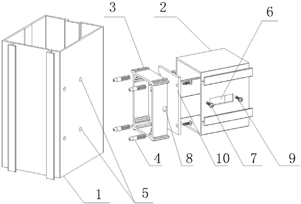
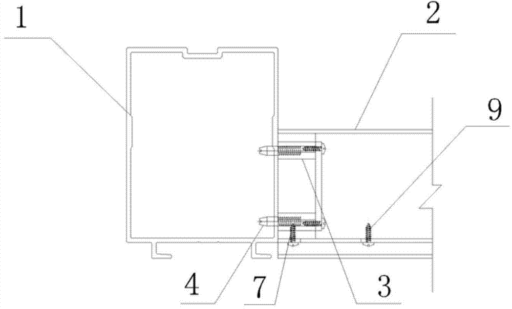
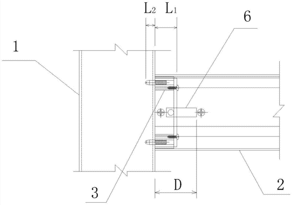
[0032] like Figure 1-Figure 3 As shown, a connection structure between a beam and a column, it includes: a column 1, a beam 2 connected to the column 1, a movable latch seat 3 is provided in the end of the beam 2, and a plurality of bolt seats are arranged on the latch seat 3 A bolt 4; a pin hole 5 corresponding to the bolt 4 is provided on the column 1; a through hole 6 penetrating the side wall is provided on the side wall at the end of the beam 2.

[0033] Wherein, the bolt seat 3 is a square frame surrounded by four side plates, and the bolt 4 is arranged at the same end of the square frame. When actually connecting the beam 2 and the column 1, first align the pin 4 with the pin hole 5, then insert a push rod into the through hole 6, and make the push rod lean against the back of the pin seat 3, and then use a hammer to hit the push rod Insert the bolt 4 into the pin hole 5 to realize the connection between the beam 2 and the column 1 . In this embodiment, in order to i...

Embodiment 2

[0040] like Figure 4 As shown, a connection structure between a beam and a column, it includes: a column 1, a beam 2 connected to the column 1, a movable latch seat 3 is provided in the end of the beam 2, and a plurality of bolt seats are arranged on the latch seat 3 A bolt 4; a pin hole 5 corresponding to the bolt 4 is provided on the column 1; a through hole 6 penetrating the side wall is provided on the side wall at the end of the beam 2.

[0041] This embodiment provides a beam-to-column connection structure, which is basically the same as Embodiment 1, the difference is that the bolt 4 is a smooth pin, and the bolt seat 3 is provided with a mounting hole for installing the pin. The pin is bonded to the mounting hole by adhesive.

Embodiment 3

[0043] like Figure 5 , Image 6As shown, a connection structure between a beam and a column, it includes: a column 1, a beam 2 connected to the column 1, a movable latch seat 3 is provided in the end of the beam 2, and a plurality of bolt seats are arranged on the latch seat 3 The bolt 4; a pin hole corresponding to the bolt 4 is provided on the column 1 .

[0044] This embodiment provides a connection structure between a beam and a column, which is basically the same as that of Embodiment 1, the difference being that the through hole in Embodiment 1 is replaced by a U-shaped opening 11, and a U-shaped opening exposed on the pin seat 3 is provided. 11 outer handle 12.

[0045] When actually connecting the beam 2 and the column 1, first align the pin 4 with the pin hole, and then push or tap the handle 12 to insert the pin 4 into the pin hole to realize the connection between the beam 2 and the column 1.


PUM


Abstract

The invention discloses a cross beam and stand column connecting structure. The cross beam and stand column connecting structure comprises a stand column and a cross beam connected with the stand column. A movable bolt base is arranged inside the end of the cross beam, and a plurality of bolts are arranged on the bolt base. The stand column is provided with bolt holes corresponding to the bolts, and the end of the cross beam is provided with a through hole penetrating through the wall of the cross beam, a limiting part for controlling the bolt base to move and a locking part for fixing the position of the bolt base. Compared with the prior art, the cross beam and stand column connecting structure has the advantages of being convenient to install and good in torsion resistance and shear-resisting performance.

Description

technical field [0001] The invention relates to the technical field of building curtain walls, in particular to a connection structure between a curtain wall beam and a column. Background technique [0002] With the rapid development of the national economy and the continuous improvement of people's living standards, a large number of curtain wall projects have sprung up all over the country. my country has become the country with the largest output and the largest curtain wall design and construction teams in the world. Compared with traditional building walls, curtain walls have many advantages such as strong modernity, lightness and clarity, rich shapes, lightening building loads, energy saving and environmental protection; at the same time, as a new building exterior decoration technology, curtain walls expand the design of architects. The space fully reflects the requirements of architectural aesthetics. However, in order to cope with the heavy engineering tasks, most...

Claims


Application Information

Patent Timeline
Patent Type & Authority Applications(China)
IPC IPC(8): E04B1/58
Inventor 杜军桦杜金泽卢发瑞
Owner 杜军桦
Why Eureka
Try Eureka