Protection net with adjustable size

A protective net and size technology, applied in the direction of shutters/movable grilles, windows/doors, building components, etc., can solve the problems of difficult standardized production, large sizes, increased costs, etc., and achieve the effect of convenient purchase

Active Publication Date: 2014-05-07
汤军
View PDF6 Cites 2 Cited by
  • Summary
  • Abstract
  • Description
  • Claims
  • Application Information

AI Technical Summary

Problems solved by technology

Its disadvantages are: its length and width can only be determined by professionals who come to measure the size of the window, which increases the cost; and there are many sizes, it is difficult to standardize production

Method used


Image

  • Protection net with adjustable size
  • Protection net with adjustable size
  • Protection net with adjustable size

Examples


Embodiment 1

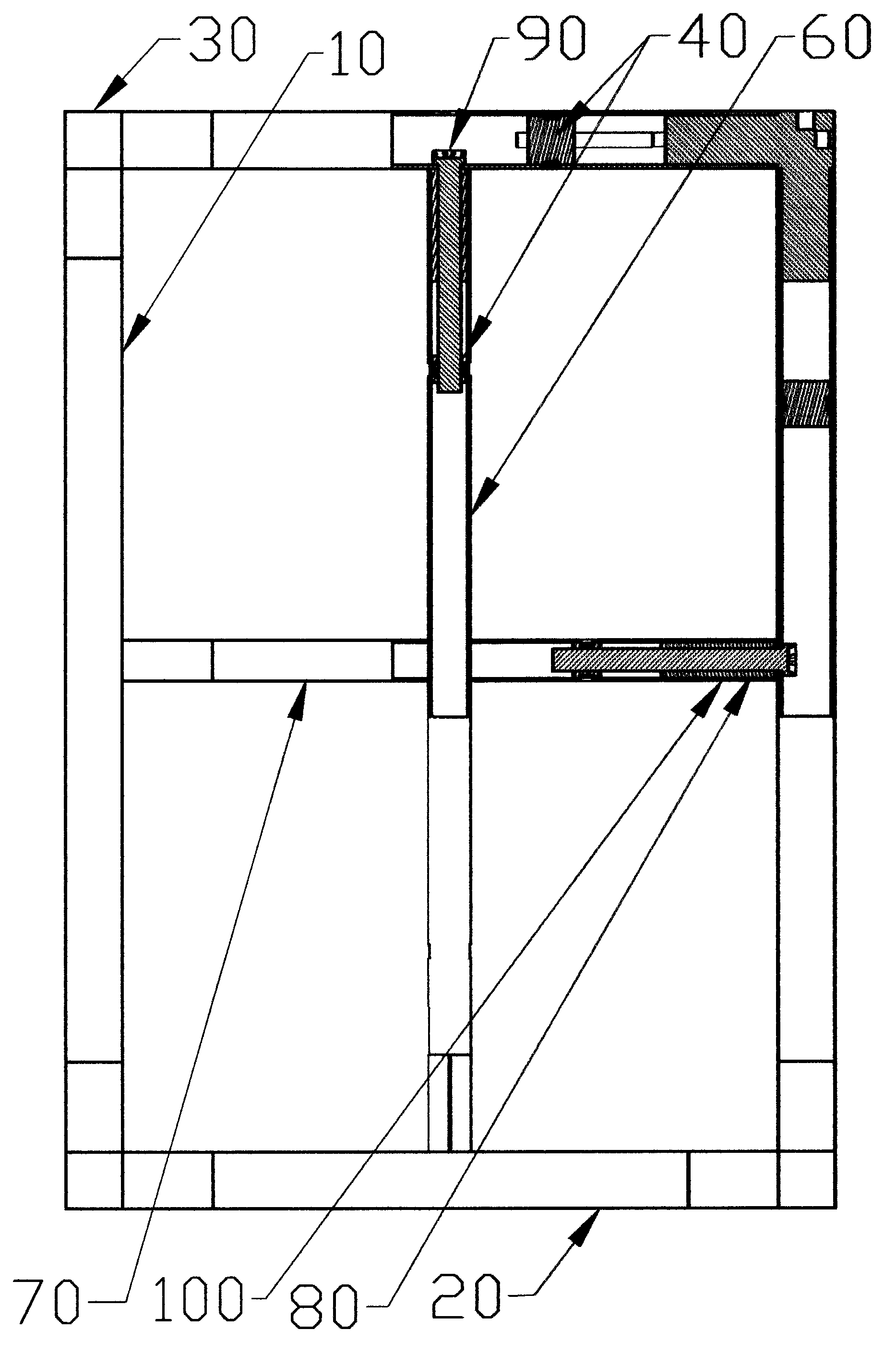
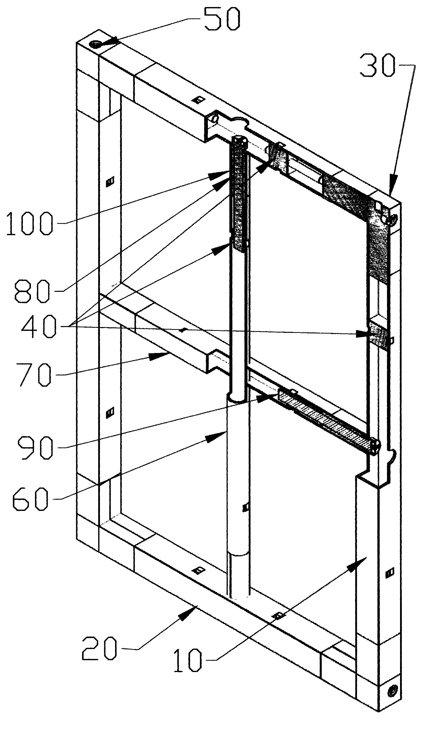
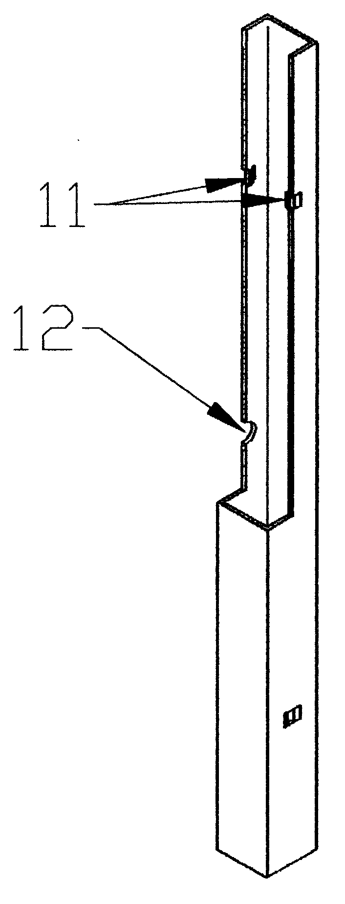
[0047] A size-adjustable protective net, as in cutaway view figure 1 , 2 As shown, it includes a mullion 10, a horizontal frame 20, a corner bracket 30, an aluminum tenon joint 40, a long bolt 50, a vertical pipe 60, a horizontal pipe 70, a threaded pipe 80, a thick bolt 90 and a sleeve 100. Wherein, the mullion is as shown in section image 3 As shown, it is a section of rectangular tube with a mortise joint structure 11 at both ends, and N through holes 12 on the rectangular tube.

[0048] Described horizontal frame 20 is as section view Figure 4 As shown, it is a section of rectangular tube with a mortise joint structure 21 at both ends, and N through holes 22 on the rectangular tube.

[0049] The angular code 30 is as Figure 5 As shown, its corner is a rectangular block 31, a lower step 32 is arranged at the bottom of the rectangular block, and a through hole 33 runs through the rectangular block 31 on the lower step 32. There is an upper step 34 next to the rectang...

Embodiment 2

[0063] Figure 15 Shown is a schematic representation of the second type of horizontal grid. Said horizontal bar such as section Figure 16 As shown, it is made up of grid bar 110, grid bar connector 120 and screw 50. There is a small protrusion in the middle of the grid bar 110 . The grid bar connector 120 is as Figure 17 As shown, there is a flat cavity 121 in the middle, a semicircular groove 122 at the bottom of the flat cavity 121, and two small protrusions 123 on the semicircular groove 122. The flat cavity 121 of the grid bar connector 120 is sleeved with the grid bar 110 . The two small protrusions 123 of the grid bar connector and the small protrusions of the grid bar 110 form a triangle and are connected by screws 50 . The screw 50 is connected with the mullion 10 at the same time.

Embodiment 3

[0065] Figure 18 Shown is a schematic representation of the third type of horizontal grid. The horizontal grid bar is composed of a grid bar 110 , a grid bar connector 130 , a locking bolt 140 , a long bolt 50 and a sleeve 150 . The grid bar 110 is a sheet with two through holes at both ends. The grid bar connector 130 is as Figure 19 As shown, there is a deep groove 131 in the middle, a pair of threaded holes 132 are arranged on the longitudinal direction of the deep groove 131, and a threaded hole 133 is respectively arranged on both sides of the deep groove 131 horizontally. The casing 150 is as Figure 20 As shown, it is a flat pass. There is a screw hole 151 on the casing. Both ends of the grid bar 110 are respectively connected to the grid bar connector 130 through locking bolts 140 . The threaded holes 133 of the grid bar connecting head 130 are connected with long bolts. The sleeve 150 covers the grid bar connector 130 and the like, and is fixed with screws.


PUM


Abstract

The invention relates to a protection net with adjustable size. The protection net comprises a vertical frame, a transverse frame, a connector, aluminum tenon joints, long bolts, a vertical pipe, a transverse pipe, threaded pipes, thick bolts and sleeves. A lower step of the connector is connected with the inner cavity of the vertical frame, through holes in the lower step are connected with the aluminum tenon joints in the vertical frame through the long bolts, an upper step is connected with an inner cavity of the transverse frame, and through holes in the upper step are connected with the aluminum tenon joints in the transverse frame through the long bolts. Tenon joint structures at two ends of the vertical pipe or the transverse pipe are connected with the aluminum tenon joints and the threaded pipes and are sleeved with the sleeves to form vertical lattice bars or transverse lattice bars, the thick bolts penetrate the through holes of the transverse frame or the vertical frame to be in threaded connection with the aluminum tenon joints in the threaded pipes and the vertical pipe. The protection net has the advantage that a professional does not need to go to each house to measure the window size, the length and the width are adjustable, specification production can be conducted, and purchase is facilitated.

Description

technical field [0001] The invention belongs to the technical field of living room decoration, in particular to a size-adjustable protective net structure. Background technique [0002] The existing protective net is generally composed of a frame and a grid, and there are three connection methods: 1. Stainless steel materials are connected by welding; 2. Aluminum alloy profiles are connected by corner codes and bolts; . The frame and grid are assembled in the factory and then shipped to the consumer. Its disadvantages are: its length and width can only be determined by professionals who come to measure the size of the window, which increases the cost; and there are many sizes, which makes it difficult to standardize production. Contents of the invention [0003] The purpose of the present invention is to provide a size-adjustable protective net that does not require professionals to come to measure the size of the window, whose length and width are adjustable, can be sta...

Claims


Application Information

Patent Timeline
Patent Type & Authority Applications(China)
IPC IPC(8): E06B9/02E06B3/964
Inventor 汤军
Owner 汤军
Why Eureka
Try Eureka