Slide switch device

A technology of sliding sleeve switch and sliding sleeve, which is applied in the direction of production fluid, wellbore/well components, earthwork drilling, etc., can solve the problems of increasing construction period and risk, and achieve unlimited fracturing stages and convenient construction Effect

Active Publication Date: 2016-03-02
CHINA PETROLEUM & CHEM CORP +1
View PDF8 Cites 0 Cited by
  • Summary
  • Abstract
  • Description
  • Claims
  • Application Information

AI Technical Summary

Problems solved by technology

The mechanical switch sliding sleeve needs to be lifted and lowered several times to open the sliding sleeve during use, which increases the construction period and risks

Method used


Image

  • Slide switch device
  • Slide switch device
  • Slide switch device

Examples


Embodiment Construction

[0029] The present invention will be further described below in conjunction with accompanying drawing.

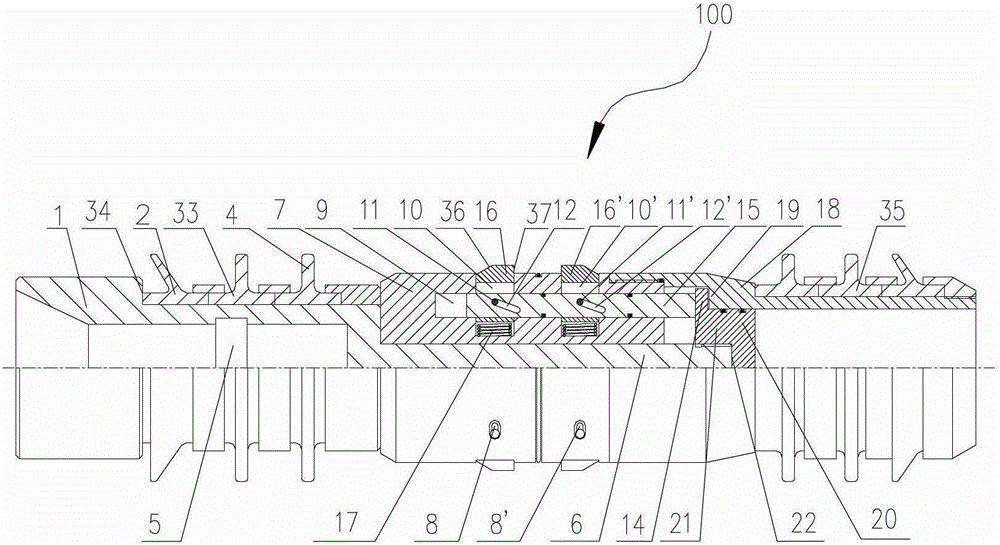
[0030] figure 1 A sliding switch device 100 according to the invention is schematically shown. The sliding switch device 100 includes: a cylindrical body 1 , which is in the shape of a stepped shaft and whose diameter gradually decreases toward the first end 6 . On the circumferential side wall of the first end 6 of the main body 1, there are provided circumferentially elongated first guide nail grooves 8, 8' penetrating the side wall, which are used to guide guide nails together with other structures described below 11, 11' movement.

[0031] The sliding switch device 100 also includes a locking block assembly mounted on the first end 6 of the body 1 . The lock block assembly includes a housing 7 slidably mounted on the first end 6 of the body 1 . In a preferred embodiment, the housing 7 is ring-shaped and sleeved on the first end 6 of the body 1 in a sliding manner. ...


PUM


Abstract

The invention relates to a sliding sleeve opening and closing device comprising a stepped-shaft-shaped cylinder body and a locking block assembly installed at a first end of the body. A cylindrical supporting sleeve is arranged at the downstream of a shell, and an end cover is arranged between the supporting sleeve and the body. According to the sliding sleeve opening and closing device, the opening series of a sliding sleeve is not limited, flow-back is convenient, and working performance is reliable.

Description

technical field [0001] The invention relates to a fracturing device, more particularly to a sliding sleeve switch device. Background technique [0002] In recent years, unconventional oil and gas resources such as shale gas and coalbed methane have become a powerful substitute for conventional oil and gas resources. Sliding sleeve staged fracturing device is an important device for the exploitation of unconventional oil and gas resources. It is widely used in fracturing stimulation of vertical wells, directional wells, and horizontal wells in shale gas, low permeability production layers, and thin oil layers. [0003] Sliding sleeve switch technology is the key technology of sliding sleeve staged fracturing. Currently commonly used sliding sleeves include ball-opening sliding sleeves, hydraulic opening sliding sleeves and mechanical switch sliding sleeves. The ball-throwing open sliding sleeve is usually used in conjunction with an open hole packer. Its working principle i...

Claims


Application Information

Patent Timeline
Patent Type & Authority Patents(China)
IPC IPC(8): E21B43/26
Inventor 李占英路保平朱玉杰
Owner CHINA PETROLEUM & CHEM CORP
Why Eureka
Try Eureka