Supercharge Your Innovation With Domain-Expert AI Agents!

Friction clutches for motor vehicles and corresponding motor vehicles

A technology for friction clutches and motor vehicles, which is applied in the field of motor vehicles and air gap devices for friction disc clutches, can solve the problems that the air gap function can no longer be completely ensured, and achieve the goal of avoiding the reduction of the friction surface and avoiding the damage of the friction surface Effect

Inactive Publication Date: 2018-06-08
SCHAEFFLER TECH AG & CO KG
View PDF8 Cites 0 Cited by
  • Summary
  • Abstract
  • Description
  • Claims
  • Application Information

AI Technical Summary

Problems solved by technology

[0004] The mechanical solutions known so far have the disadvantage that when designing the air-gap means the structural gap is relatively limited and, moreover, the corresponding forces exerted by the air-gap means can only be specified to a very limited extent.
When realized by magnets, vibrations in the motor vehicle cause the corresponding magnets to slowly demagnetize, so that the air gap function can no longer be completely ensured

Method used


Image

  • Friction clutches for motor vehicles and corresponding motor vehicles
  • Friction clutches for motor vehicles and corresponding motor vehicles
  • Friction clutches for motor vehicles and corresponding motor vehicles

Examples


Embodiment Construction

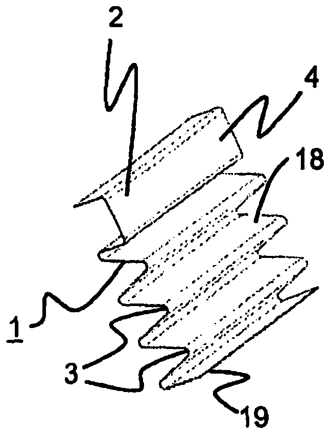
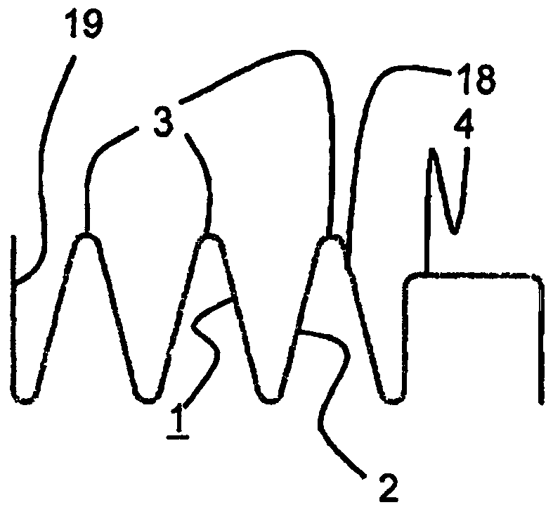
[0039] figure 1 and 2 A schematic view and a sectional view of the compression spring-like element 1 are shown schematically. The compression spring-like element 1 consists of a thin plate 2 . Sheet metal 2 is in particular a sheet metal made of spring steel. The compression spring-like element 1 is here produced by shaping the sheet metal 2 , wherein a plurality of folds 18 and thus inflection points 3 are formed, which are not completely assigned reference numerals for reasons of clarity. The compression spring-like element 1 has a contour with at least one inflection point 3 . In this case, inflection point 3 is to be understood as the point at which the contour of the compression spring-like element 1 changes its curvature, ie transitions from a "right turn" to a "left turn" or from a "left turn" Transition to "Right Turn". Furthermore, the compression spring-like element 1 also includes a connecting region 4 for a form-locking connection with a corresponding contact ...


PUM


Abstract

The clutch has a friction element with an input shaft and another friction element with an output shaft connected in a rotationally fixed manner. The friction elements of a friction package are alternatively arranged in a direction of a rotational axis. A pressure spring-like element (1) applies spring force in the direction of the rotational axis and is arranged between the two friction elements adjacent in the direction of the rotational axis. The pressure spring-like element is formed from a metal sheet (2) such that a contour of the spring-like element exhibits a turning point (3). An independent claim is also included for a motor car.

Description

technical field [0001] The invention relates to a friction clutch for a motor vehicle and to a corresponding motor vehicle. In particular, the invention relates to an air gap arrangement for a friction plate clutch. Background technique [0002] In so-called friction plate clutches, the frictional transmission of torque from the input shaft to the output shaft is effected by means of a large number of friction partners, also called friction plates, of which the first group (first friction partner parts) are non-rotatably connected to the input shaft of the friction clutch. In this case, the clutch can be engaged or engaged by moving the friction partners relative to each other in the direction of the axis of rotation of the shaft and pressing them against each other. The disengagement or disengagement of the friction clutch takes place by corresponding counter-movements of the first friction partner and the second friction partner. If nothing else is done, when disengagin...

Claims


Application Information

Patent Timeline
Patent Type & Authority Patents(China)
IPC IPC(8): F16D13/64F16D13/70
CPCF16D13/52F16D13/69
Inventor M·芬肯策勒
Owner SCHAEFFLER TECH AG & CO KG
Features
  • R&D
  • Intellectual Property
  • Life Sciences
  • Materials
  • Tech Scout
  • Unparalleled Data Quality
  • Higher Quality Content
  • 60% Fewer Hallucinations
Learn More