Air compressor clutch

A technology for air compressors and clutches, applied to clutches, non-mechanical drive clutches, magnetic drive clutches, etc., to achieve the effects of improving compressor life, reducing development costs, and improving vibration problems

Inactive Publication Date: 2014-05-07
HUNAN UNIV AISHENG AUTO TECH DEV
View PDF6 Cites 0 Cited by
  • Summary
  • Abstract
  • Description
  • Claims
  • Application Information

AI Technical Summary

Problems solved by technology

[0004] The invention designs a new electromagnetic clutch, which is a new clutch invented on the traditional air compressor. The clutch has a buffering effect on the pulse excitation, and converts the key excitation at the start-up time of the transmission compressor into a flexible force, which solves the vibration at the start-up time of the automobile air conditioner. The big problem is to improve the NVH performance of the whole vehicle and improve the comfort of the occupants. It can solve the above-mentioned rigid dynamic problem at the moment of clutching and disengaging. At the same time, considering the cost and feasibility of the new structure, the present invention discloses two technical solutions, see Example 1 and Example 2

Method used


Image

  • Air compressor clutch
  • Air compressor clutch
  • Air compressor clutch

Examples


Embodiment 1

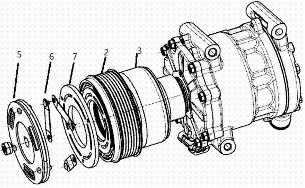
[0033] figure 2 It is a schematic diagram of an air compressor with an improved structure according to Embodiment 1 of the present invention. It is mainly composed of a driven plate 5, a leaf spring 6, a pressure plate 7, a belt pulley 2, an electromagnetic coil 3 and a compressor cylinder. The driven plate 5 , a leaf spring 6, a pressure plate 7, a belt pulley 2, and an electromagnetic coil 3 are sequentially connected along the direction of the main axis of the compressor, wherein the connection installation of the electromagnetic coil 3 and the belt pulley 2 is the same as that of a traditional compressor.

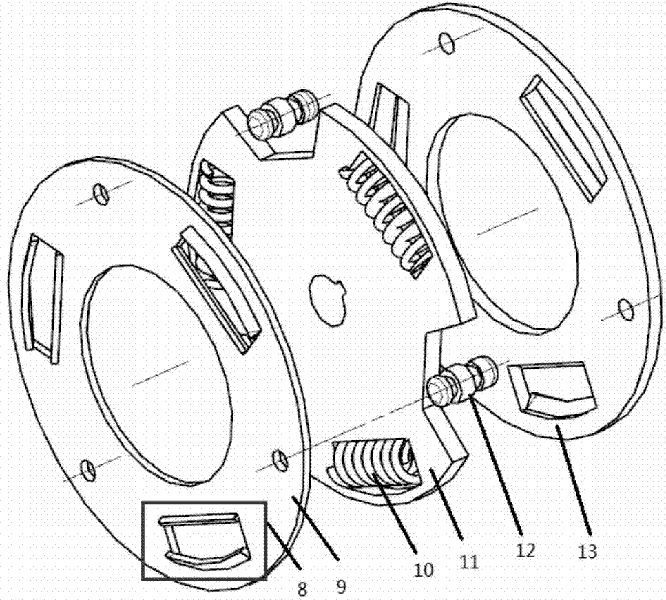
[0034] image 3 for figure 2 The structural schematic diagram of the driven disc 5 in , it can be seen that the driven disc 5 is composed of two driven outer plates 9 and 13, an inner plate 11, a coil spring 10 and a limit rivet 12, wherein the inner plate 11 The central hole is connected with the main shaft of the compressor through a key; the coil springs 10 are r...

Embodiment 2

[0039] Image 6 It is a schematic diagram of an air compressor with an improved structure according to Embodiment 2 of the present invention. The system device is mainly composed of a return spring 16, a driven plate 17, a belt pulley 2, an electromagnetic coil 3 and a compressor cylinder. The return spring 16 , the driven disk 17, the belt pulley 2, and the electromagnetic coil 3 are sequentially connected along the direction of the main shaft of the compressor, wherein the connecting installation mode of the electromagnetic coil 3 and the belt pulley 2 is basically the same as that of a traditional compressor.

[0040] Figure 7 It is a schematic diagram of the driven disc 17 according to Embodiment 2 of the present invention, which is mainly composed of a driven disc outer plate 9 , a coil spring 10 , an inner plate 11 , rivets 18 and a driven disc pressing plate 19 . The inner plate 11 is connected to the main shaft of the compressor through a connection key, the coil spr...


PUM


Abstract

The invention relates to an air compressor clutch. The air compressor clutch is characterized in that a force buffering component is added in a compressor transmitting system structure, at the beginning of the vibration, the force buffering component absorbs energy, stored energy is released through the force buffering component after a compressor main shaft reaches a specific rotating speed, the clutch has a buffer effect on impulse excitation, key excitation at the moment when a compressor is driven to be started is converted into flexibility force, the problem that the vibration of an automotive air conditioner is large at the starting moment is solved, the NVH performance of a complete vehicle is improved, the comfort level of passengers is improved, the problem of clutch instantaneous rigid power is solved, and the new structure cost and feasibility are considered at the same time.

Description

technical field [0001] The invention relates to an air compressor clutch, which belongs to the technical field of automobile air-conditioning system compressors, and in particular relates to a new structure of an air compressor clutch NVH. Background technique [0002] The function of the car air conditioning system is to combine the air-conditioning device and the heating device to adjust the over-temperature of the air in the car, so that the car is always comfortable. The air compressor is the heart of the refrigeration cycle system, consisting of an electromagnetic clutch driven disc, a belt pulley, an electromagnetic coil and a compressor cylinder (such as figure 1 ). Part of the power of the engine is transmitted to the compressor pulley through the belt, so that the pulley is always in rotation. When the air conditioner is started, the electromagnetic coil is energized, the driven plate of the electromagnetic clutch engages the belt pulley, and rotates with the belt...

Claims


Application Information

Patent Timeline
IPC IPC(8): F16D27/108F16D27/14
Inventor 何智成王彬周恩临潘能贵余志南
Owner HUNAN UNIV AISHENG AUTO TECH DEV
Why Eureka
Try Eureka