gate

A gate valve and valve body technology, applied in the field of valves, can solve the problems of insufficient stability of the valve stem, discounted sealing effect, poor sealing effect, etc., and achieve the effect of stable movement, not easy to fall off, and reduce the probability of falling off

Active Publication Date: 2016-03-16
NINGBO TIANJILONG INTELLIGENT CONTROL TECH
View PDF6 Cites 0 Cited by
  • Summary
  • Abstract
  • Description
  • Claims
  • Application Information

AI Technical Summary

Problems solved by technology

[0004] However, even after adopting the aforementioned improvement, the gate valve still has the following defects: 1. The gate plate may be worn out after a while, so that the inclination of the gate plate and / or the sealing slope changes, and then The sealing effect is greatly reduced; 2. Because the valve stem rotates continuously or has a tendency to rotate, the sealing effect of the joint between the upper part of the valve stem and the valve body is poor; 3. In the screw nut mechanism, the outer thread of the screw and the nut There is a processing error between the internal threads of the screw, so there is a fit gap between the screw and the nut, which makes the movement of the valve stem not stable enough; 4. The gasket that inevitably exists on the sealing slope is easy to be washed away by the medium

Method used


Image

  • gate

Examples


Embodiment Construction

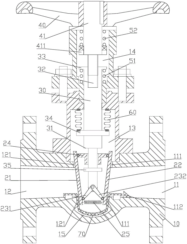
[0017] Examples, see figure 1 Shown: a gate valve, including a valve body 10, the lower part of the valve body 10 has a feed port 11 and a discharge port 12, and the left end face of the feed port 11 has a right sealing slope 111, and the right end face of the discharge port 12 has a The left sealing inclined surface 121 , a matching cavity 15 is provided between the lower part of the left sealing inclined surface 121 and the lower part of the right sealing inclined surface 111 . Simultaneously, the gate valve includes gate plates matched with the left and right sealing slopes 121 and 111 on the left and right sides, and a valve stem 30 is connected to the gate plate, and a handle 40 is arranged above the valve stem 30 . Apparently, the matching cavity 15 is used to make the lower part of the gate have an accommodation space when the gate is translated downwards and then sealed with the sealing slope.

[0018] Further speaking:

[0019] The shutter includes a left plate body...


PUM


Abstract

The invention discloses a gate valve which comprises a valve body, a feed inlet, a discharging outlet, a right sealing inclined face, a left sealing inclined face and a gate plate. A valve rod is connected to the gate plate. A handle is arranged above the valve rod. The gate plate comprises a left plate body with the left side face matched with the left sealing inclined face and a right plate body with the right side face matched with the right sealing inclined face. Meanwhile, a left connecting rod made of rigid materials is connected to the lower portion of the right side face of the left plate body, and a right connecting rod made of rigid materials is connected to the lower portion of the left side face of the right plate body. The upper end of left connecting rod and the upper end of the right connecting rod are both hinged to the lower end of the valve rod. The sum of the length of the left connecting rod and the length of the right connecting rod is larger than the distance between the lower portion of the left sealing inclined face and the lower portion of the right sealing inclined face. A connecting sleeve is arranged on the lower portion of the valve rod in a sliding mode. The upper portion of the right side face of the left plate body and the upper portion of the left side face of the right plate body are respectively hinged to the left side and the right side of the connecting sleeve, and a tension spring is connected between the lower portion of the left plate body and the lower portion of the right plate body. The gate valve has the advantages of being good in sealing effect.

Description

technical field [0001] The invention relates to the technical field of valves, in particular to a gate valve. Background technique [0002] Gate valve is currently the most important type of valve, which is widely used in the circulation and cut-off of liquid, gas, dust and other media. Usually, the gate valve includes a valve body, the lower part of the valve body has a feed port and a discharge port, and the left end of the feed port and the right end of the discharge port both have sealing surfaces, and the dynamic sealing fit between the two sealing surfaces There is a gate that can move up and down without rotation. Simultaneously, a valve stem is connected to the top of the flashboard, and a handle is connected to the top of the valve stem through a screw nut mechanism. That is, after the handle is rotated, the screw nut mechanism drives the valve stem to move up and down, and then the gate plate moves up and down to seal or open the two sealing slopes, finally formi...

Claims


Application Information

Patent Timeline
Patent Type & Authority Patents(China)
IPC IPC(8): F16K3/16F16K3/30F16K41/00
CPCF16K3/0209F16K3/0227F16K3/14F16K3/314F16K27/047
Inventor 孙得浩易松达李洪峰王昌林
Owner NINGBO TIANJILONG INTELLIGENT CONTROL TECH
Why Eureka
Try Eureka