
Parallel cavity type solar thermal collector

A technology of solar heat collectors and heat collectors, applied in the field of parallel cavity solar heat collectors, can solve the problems of poor antifreeze performance of plate heat collectors, high breakage rate of glass pipe fittings, unsuitable for use in northern regions, etc., and achieve improvement Heat collection and heat exchange efficiency, good heat preservation effect, and good frost resistance

Inactive Publication Date: 2014-05-07
YIKEBO ENERGY TECH SHANGHAI
View PDF9 Cites 0 Cited by
  • Summary
  • Abstract
  • Description
  • Claims
  • Application Information

AI Technical Summary

Problems solved by technology

The plate collector is cost-effective, the heat absorption and heat transfer interface is relatively flat, the energy distribution is relatively uniform, there are no hot spots in the entire interface, the overall heat transfer is relatively uniform, and the service life is long. Therefore, the plate collector occupies an important position in the solar thermal field. important position, but the plate collector has poor frost resistance and is not suitable for use in northern regions
The vacuum heat collecting tube can withstand low temperature -30 degrees Celsius, but the damage rate of the glass pipe fittings is high, and the low temperature performance is poor. The vacuum heat collecting tube of the direct current method has the danger of bursting in summer
The efficiency of the heat pipe vacuum collector is better, but there is also the danger of the glass tube being easily broken. Therefore, there is no universal and cost-effective solar collector.

Method used


Image

  • Parallel cavity type solar thermal collector
  • Parallel cavity type solar thermal collector
  • Parallel cavity type solar thermal collector

Examples


Embodiment Construction

[0021] In the following description, many technical details are proposed in order to enable readers to better understand the application. However, those skilled in the art can understand that without these technical details and various changes and modifications based on the following implementation modes, the technical solution claimed in each claim of the present application can be realized.

[0022] In order to make the purpose, technical solution and advantages of the present invention clearer, the following will further describe the implementation of the present invention in detail in conjunction with the accompanying drawings. The same or similar components in the figures are denoted by the same reference numerals.

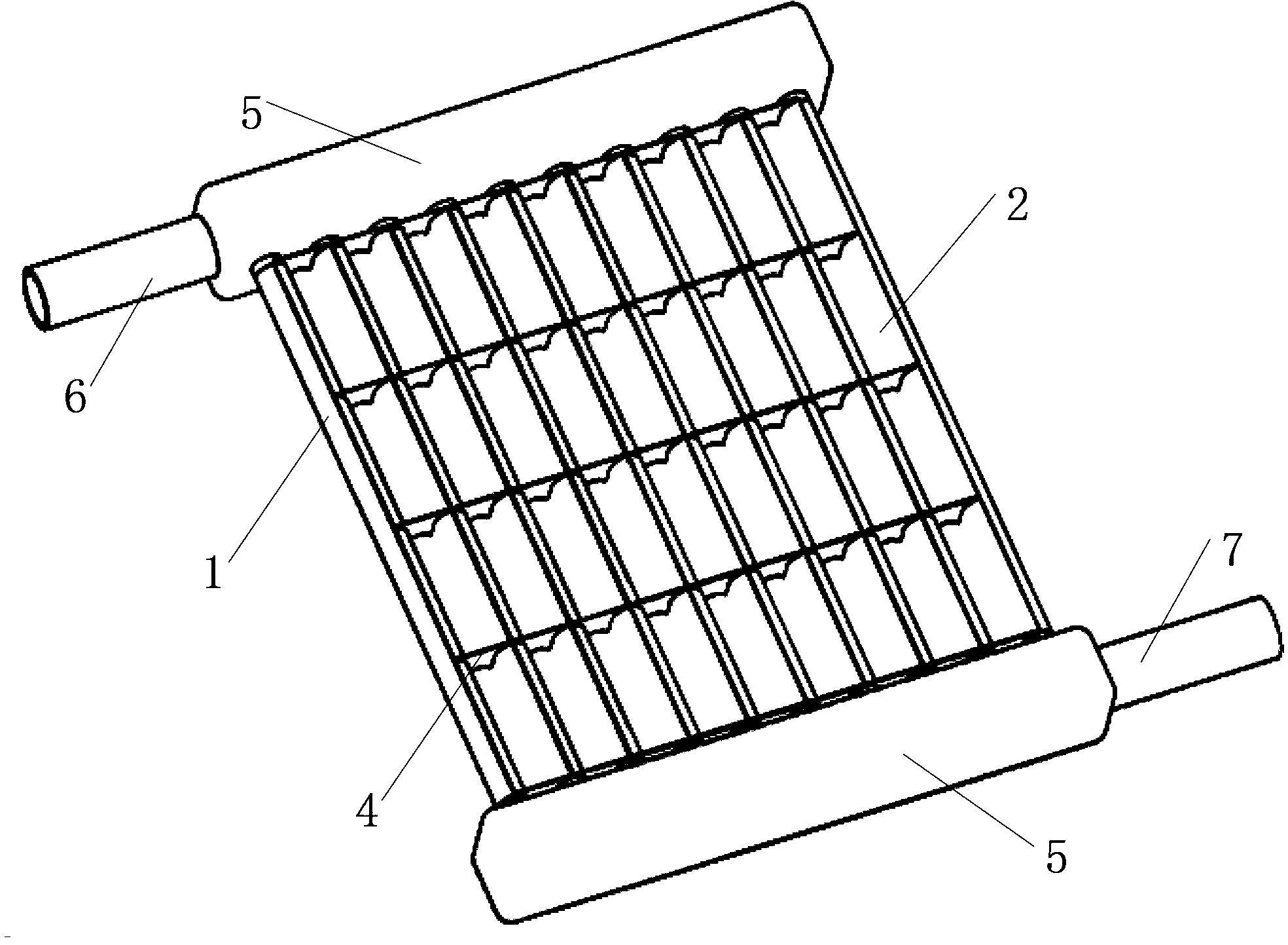
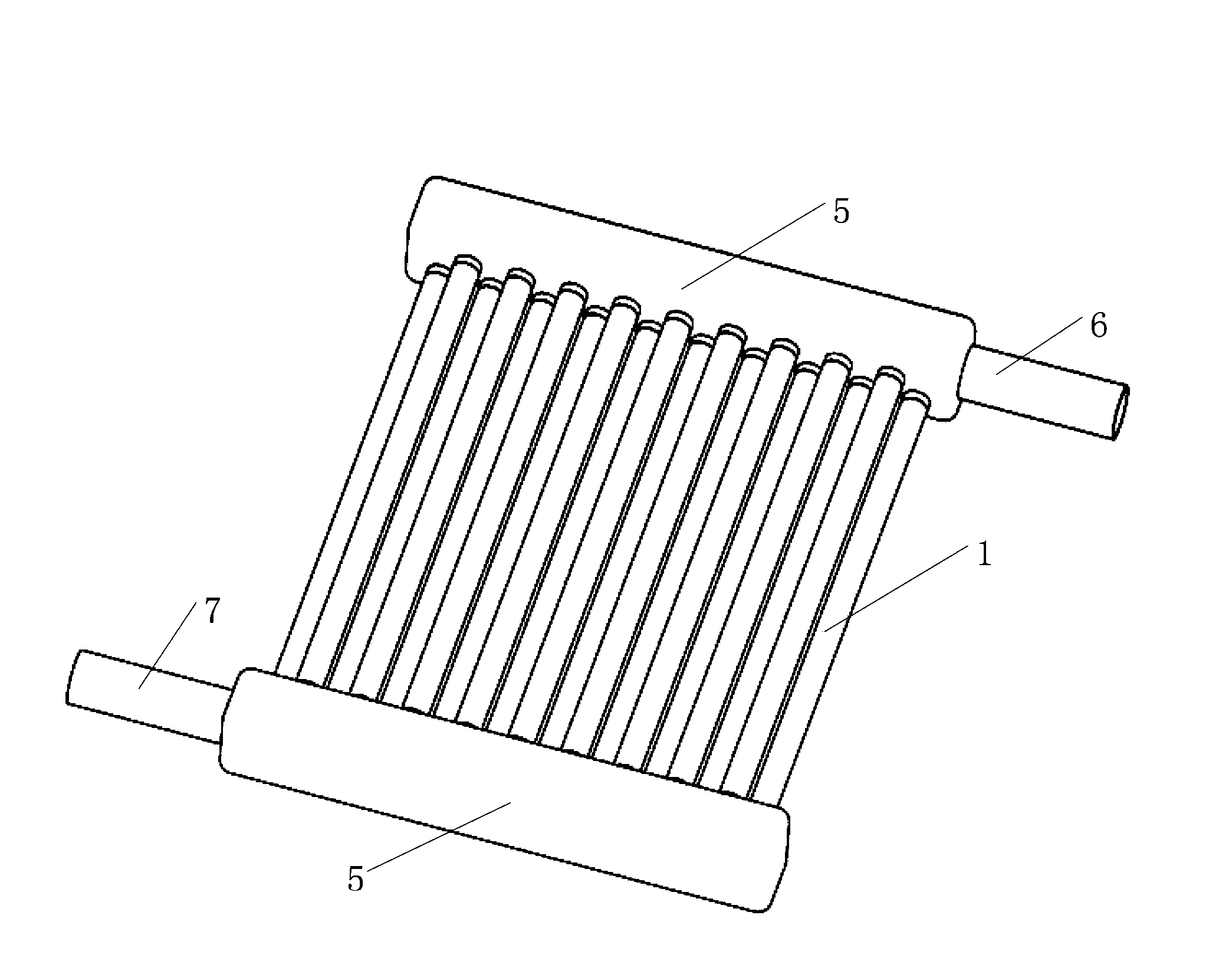
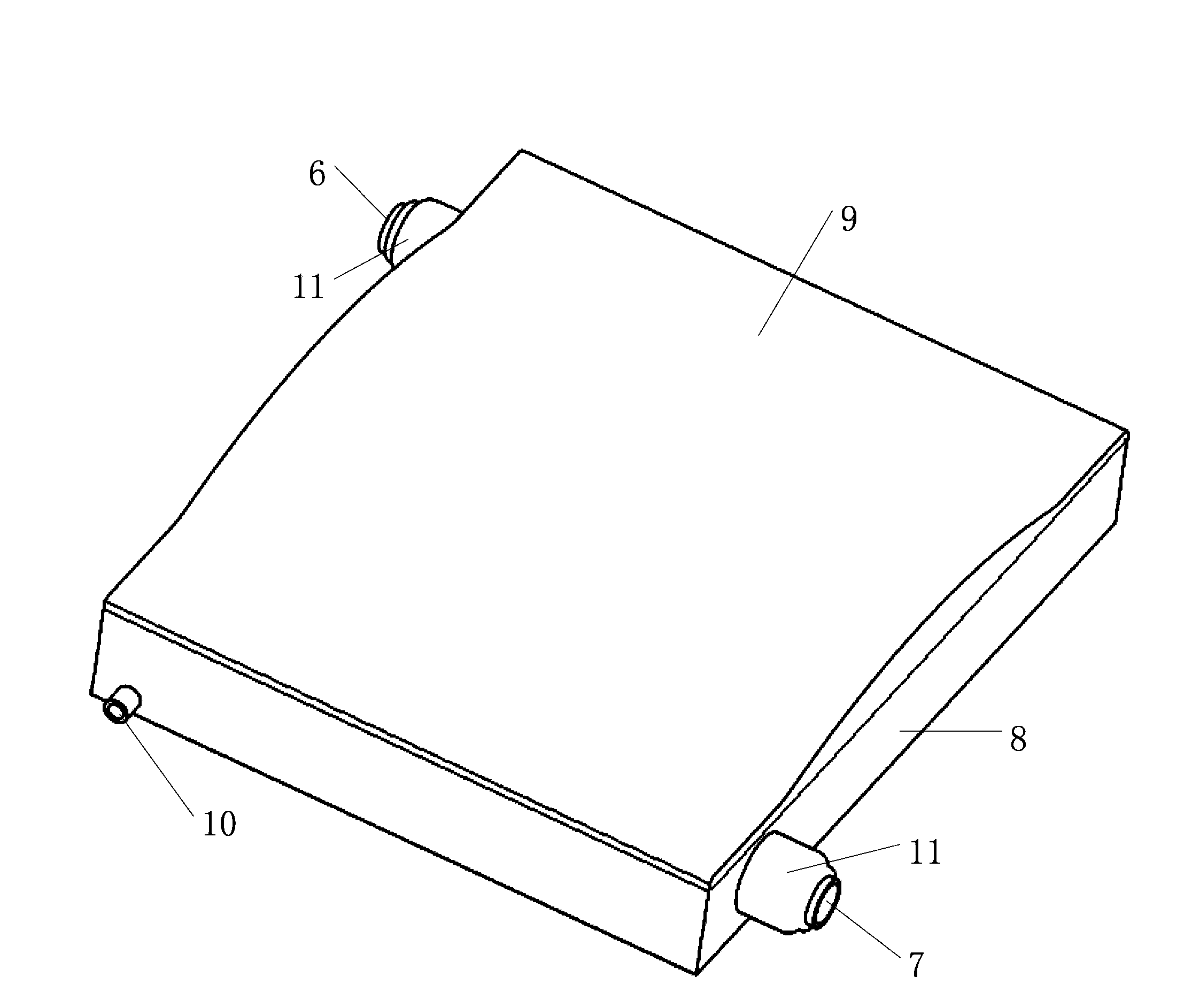
[0023] see figure 1 and figure 2 , is a structural schematic diagram of the light-receiving surface and the backlight surface of an embodiment of the parallel-cavity solar collector. The parallel-cavity solar heat collector includes: a plurality of pipeli...


PUM


Abstract

The invention relates to the technical field of solar-thermal power generation, and discloses a parallel cavity type solar thermal collector. The parallel cavity type solar thermal collector comprises a plurality of parallel pipelines which are connected in parallel, and heat absorption fins which are tightly attached to the surfaces of the pipelines and serve as parallel groove type heat absorption cavities, wherein the surfaces of the heat absorption fins are coated with selective absorption coatings. The temperature of the heat exchange surfaces can be more evenly distributed through the parallel groove heat absorption cavity type structure, and therefore the heat collection efficiency and the heat exchange efficiency of the solar thermal collector are improved, the parallel pipelines which are connected in parallel are small in flow resistance, the temperature rise problem is solved through the circulating heating, and the manufacturing process and the heat preservation process are simplified.

Description

technical field [0001] The invention relates to the technical field of solar photothermal power generation systems, in particular to a parallel cavity solar heat collector. Background technique [0002] Energy is the foundation of social development and human progress. With the continuous development of industry and the expansion of human needs, the energy situation is becoming increasingly tense, and green energy is considered to be a way to fundamentally solve human energy needs. [0003] Among them, solar energy is considered to be one of the most potential new energy sources because of its unlimited "reserves", universal distribution, cleanliness and economy. The characteristics of solar thermal power generation are good adaptability to the grid, high photoelectric conversion rate, environmental protection and adjustable, etc., so it has become an important development direction of solar energy utilization. [0004] The key to solar thermal power generation is to accum...

Claims


Application Information

Patent Timeline
Patent Type & Authority Applications(China)
IPC IPC(8): F24J2/05F24J2/26F24J2/46F24J2/48F24J2/50F24J2/51F24S10/40F24S10/75
CPCY02E10/44
Inventor 项晓东
Owner YIKEBO ENERGY TECH SHANGHAI
Learn More