Eureka AIR delivers breakthrough ideas for toughest innovation challenges, trusted by R&D personnel around the world.

Double-ridge dynamically-adjustable orienting device and adjusting method thereof

A directional device and double-roof technology, applied in installation, optics, instruments, etc., can solve problems such as high cost, high manufacturing process level, and large quantities, and achieve a stable and unchanged effect

Active Publication Date: 2014-05-07
NO 60 RES INST OF GENERAL STAFF DEPT PLA
View PDF5 Cites 0 Cited by
  • Summary
  • Abstract
  • Description
  • Claims
  • Application Information

AI Technical Summary

Problems solved by technology

[0002] In the plane, the outgoing light direction of the conventional dihedral mirror does not change with the swing of the mirror assembly, and will remain parallel (as shown figure 1 ); in the three-dimensional space, the cube-corner prism can direct the incident light back, and the incident light and the outgoing light are in a parallel state, and are not affected by the shaking posture of the prism (as shown figure 2 ), the corner cube prism has a large number of applications in engineering technology; the optical sighting device is a kind of optical lens imaging, and the target image is refracted to the specified display plane through the above-mentioned dihedral mirror and cube corner cube prism; Sighting equipment is a kind of optical sighting equipment, which is installed on some special-purpose vehicles to meet the needs of these vehicles to observe and aim at the target while moving, but the current vehicle-mounted optical sighting equipment is in this It is still difficult to obtain stable and reliable observation results in the application environment where the vehicle is shaking, so when using the current vehicle-mounted optical sighting equipment, it is still necessary to stop the vehicle first and then measure;
[0003] In response to this problem, many research units have also carried out relevant technical research, for example: "Research and Design of Vehicle-mounted Real-time Video Stabilization System" published by China North Vehicle Research Institute on "Computer Measurement and Control" 2007.15 (7), page 922 , the design uses multiple electronic control technologies such as electronic image stabilization, inertial technology image stabilization and video image stabilization to achieve image stabilization for motion viewing and aiming. This design requires a large number of electronic components to work together, with complex structure, high cost, and manufacturing process The level requirements are also very high

Method used


Image

  • Double-ridge dynamically-adjustable orienting device and adjusting method thereof
  • Double-ridge dynamically-adjustable orienting device and adjusting method thereof
  • Double-ridge dynamically-adjustable orienting device and adjusting method thereof

Examples


Embodiment 1

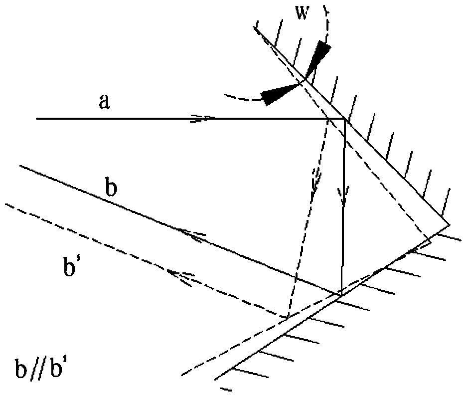
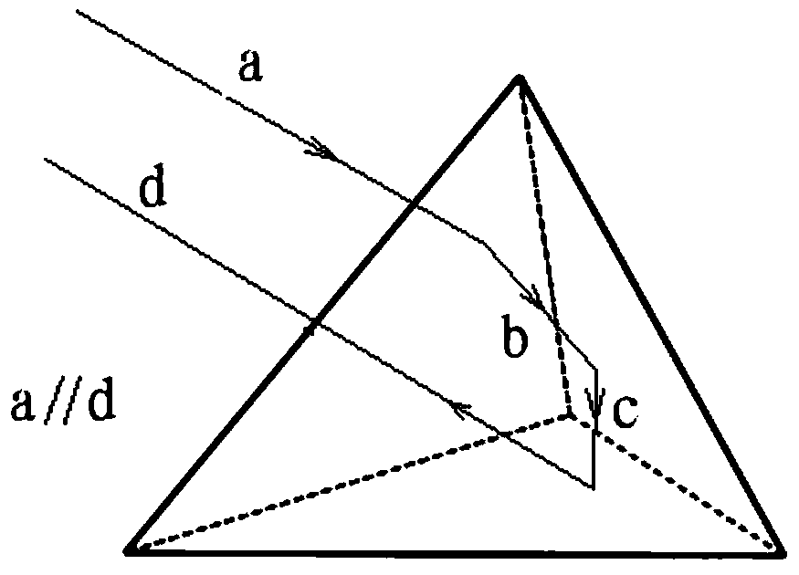
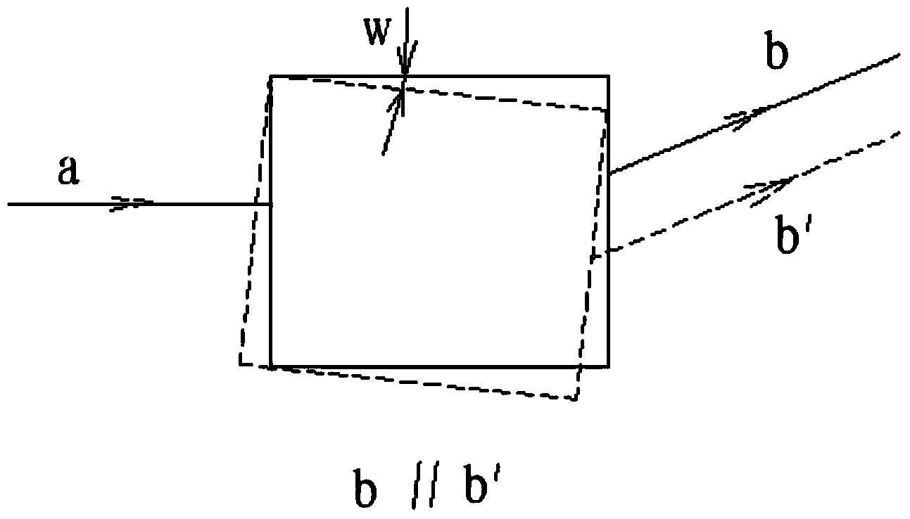
[0024] This device is Figure 4 As shown, it consists of roof prism 1, transflective roof mirror group 2, prism base 3, transflective roof frame 4, fixed platform 5, height adjustment bracket 6, height adjustment connecting rod 7, level adjustment plate 8, height motor 9, level Composed of motor 10, etc., the roof prism 1 is fixedly installed in the prism seat 3, the prism seat 3 and the height adjustment connecting rod 7 are rigidly connected, and after synthesis, they are installed on the height adjustment frame 6, and the prism seat 3 can surround the joint of the height adjustment frame 6 Rotate, the rotation is driven by the height motor 9; the height adjustment frame 6 is installed on the level adjustment plate 8, and the roof prism 1 can be adjusted and rotated in the horizontal direction under the drive of the horizontal motor 10; the transflective roof mirror group 2 is composed of two plane lenses Composition of mirror 11, the surface of plane transflective mirror 11...


PUM


Abstract

The invention discloses a light ray direction adjusting device, and particularly relates to a double-ridge dynamically-adjustable orienting device. The double-ridge dynamically-adjustable orienting device comprises a light ray steering device and a fixing platform. The light ray steering device is fixed to the fixing platform and comprises a ridge prism and a transflective ridge lens set, the ridge prism and the transflective ridge lens set are respectively provided with a light ray incident face and a light ray exit face, and the light ray exit face of the ridge prism corresponds to the light ray incident face of the transflective ridge lens set. The ridge prism and the plane transflective lens are ingeniously combined, so that parallel light rays from the remote position are transmitted forwards through the double-ridge dynamically-adjustable orienting device, the direction of the light rays are not changed along with swinging of the device, and directional adjustment is conducted if necessary.

Description

technical field [0001] The invention relates to a light direction adjusting device, specifically a double-ridge dynamically adjustable orientation device, and also relates to an adjusting method of the device. Background technique [0002] In the plane, the outgoing light direction of the conventional dihedral mirror does not change with the swing of the mirror assembly, and will remain parallel (as shown figure 1 ); in the three-dimensional space, the cube-corner prism can direct the incident light back, and the incident light and the outgoing light are in a parallel state, and are not affected by the shaking posture of the prism (as shown figure 2 ), the corner cube prism has a large number of applications in engineering technology; the optical sighting device is a kind of optical lens imaging, and the target image is refracted to the specified display plane through the above-mentioned dihedral mirror and cube corner cube prism; Sighting equipment is a kind of optical si...

Claims


Application Information

Patent Timeline
IPC IPC(8): G02B7/18G02B7/198
Inventor 吕战强裴少俊薛汝东赵志立彭海峰陈金业储晔其他发明人请求不公开姓名
Owner NO 60 RES INST OF GENERAL STAFF DEPT PLA
Why Eureka
Eureka Blog
Learn More