Eureka AIR delivers breakthrough ideas for toughest innovation challenges, trusted by R&D personnel around the world.

Speed control device

Inactive Publication Date: 2007-01-18
9058 3717 QUEBEC SYRKOSS
View PDF18 Cites 1 Cited by
  • Summary
  • Abstract
  • Description
  • Claims
  • Application Information

AI Technical Summary

Benefits of technology

[0006] An advantage of the present invention is that the speed control device for the skate engages a wheel to provide gentle and gradual decelerative action thus avoiding premature deterioration of the friction pads and / or user-controlled speed deceleration.
[0007] Another advantage of the present invention is that the speed control device allows for adjustment to accord with the physical characteristics of the skate, the personal skill level of the user and prevailing weather conditions.
[0008] A further advantage of the invention resides in the contact as between the frictional pad and the wheel to give, upon actuation of the device a controlled decelerative effect gradually to bring the wheel and thus the skate to a stop.
[0009] A still further advantage of the present invention is that the speed control device is capable of automatic disengagement from the wheel when the latter has become stationary at the complete stop of the skate or when the braking wheel is momentarily disengaged from the ground surface.
[0010] Another advantage of the present invention is that the speed control device is activated by the user only once, raising the front portion of the skate (as typically with ground engaging brakes), but once engaged the device remains engaged during rotation of the wheel.
[0011] Still another advantage of the invention is that the speed control device, once in operation after activation, allows the user to remain stable on the skates with all wheels engaging the ground surface while the device remains in operation.

Problems solved by technology

Typically, the user may not apply enough pressure to the brake pad resulting in too slow a stop or conversely, in applying excessive pressure too abrupt a halt would be achieved and both extremes could result in loss of control with possible injury.
For example, when going downhill, it is almost impossible for a user to continuously maintain the brake in operation with the front part of the skate raised, especially for a beginner level skater that could easily panic and injure himself before reaching the low bottom of the hill.
In addition, most braking devices being non-adjustable may have too sharp an efficiency curve thereby precluding any gradual speed reducing effect and again the user needs to acquire the requisite skills on a trial and error basis.
Some other forms of braking device provide for the application of a braking pressure on the running surface of the wheels, often resulting in damage and deterioration of the wheels with a concomitant and high replacement cost.
Furthermore, the absence of any adjustment capability precludes any opportunity on the part of the user to become adept quickly at the deployment of the braking device.
Moreover, the lack of adjustability means that the device cannot cater for fluctuating weather conditions that affect blading performance.
Finally, braking devices are usually an integral part of the roller blade and thus cannot be changed.

Method used


Image

  • Speed control device
  • Speed control device
  • Speed control device

Examples


Embodiment Construction

[0029] With reference to the annexed drawings the preferred embodiments of the present invention will be herein described for indicative purpose and by no means as of limitation.

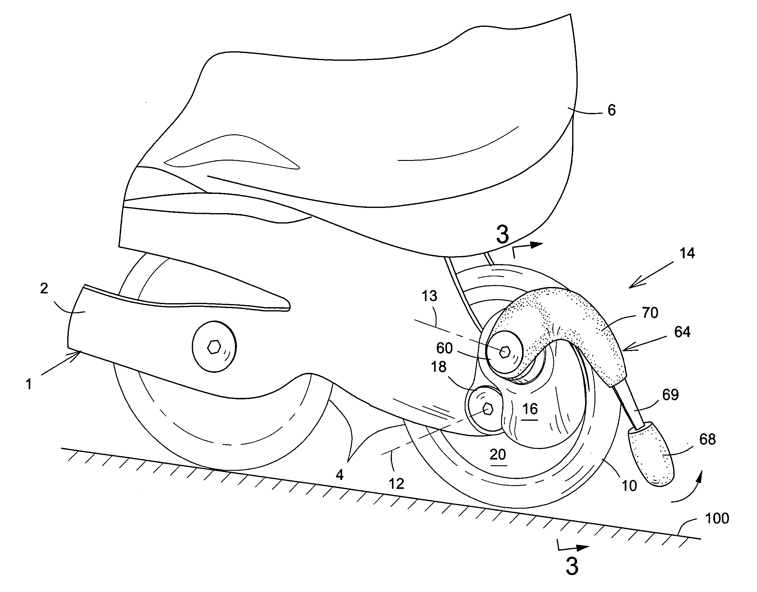
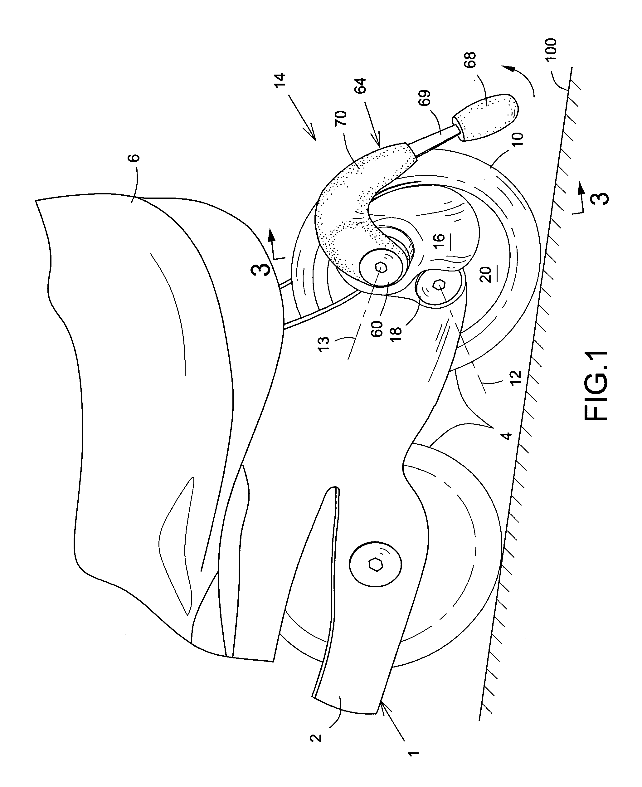
[0030] Referring to the drawings, a speed control device 14 in accordance with an embodiment of the present invention is shown in relation to a roller skate blade only part of which is generally shown at 1 including a wheel frame 2 provided with a number of wheels 4 only two being illustrated in the drawing for the sake of clarity. Surmounting the frame 2 is a boot 6 for accommodation of a user's foot.

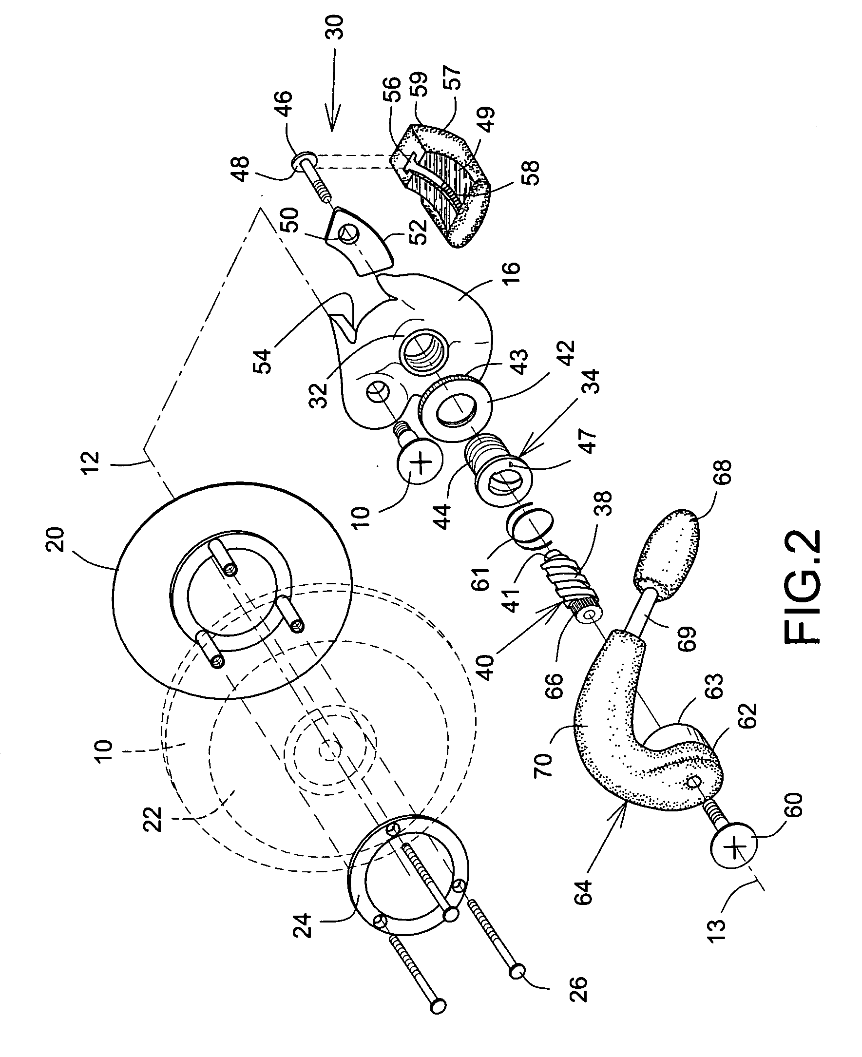
[0031] The rearmost wheel 10 is rotatably mounted on a fixed axle 12, as is a speed control device 14 a housing 16 of which is secured to the axle 12 by means of a screw 18. A brake disc 20 is typically affixed to the hub 22 of the wheel 10 by means of a mounting ring 24 and suitably secured by three screws 26.

[0032] The housing 16 of the device 14 has a brake mechanism 30 or actuator eccentrically and typic...


PUM


Abstract

A speed control device suitable for roller skates includes a wedge-shaped floating brake pad actuable into an operative mode in a frictional contact with a disc secured to a blade wheel by means of an actuating lever movable in a controlled manner through the agency of mating scroll formations. The brake pad being configured and sized to, once frictionally engaged with the disc, remain engaged therewith until rotation of the wheel substantially ceases.

Description

FIELD OF THE INVENTION [0001] The present invention relates to a speed control device and in particular, but not exclusively, has reference to such a device suitable for use on a roller skate, more especially a roller blade. BACKGROUND OF THE INVENTION [0002] In-line roller blades are now in common use and, for recreational and even practical purposes, have virtually supplanted the conventional roller skates of yore. Roller blades typically include a boot portion to house the foot of the user comfortably surmounting a narrow frame running along the base of the boot to accommodate a number of wheels aligned for rotation along a common plane. It is relatively commonplace for some form of braking device to be connected to the rear part of the frame, but they demand some degree of acquired skill and coordination for effective and safe operation. In some models, the device requires the user to raise the front part of the skate to engage a brake pad located at the back part of the skate w...

Claims


Application Information

Patent Timeline
IPC IPC(8): A63C17/14
CPCA63C17/1436A63C17/06
Inventor SYRKOS, YVES
Owner 9058 3717 QUEBEC SYRKOSS
Why Eureka
Eureka Blog
Learn More