Brake control device for a brake system of a rail vehicle, brake system, rail vehicle and method for operating a brake control device

A technology of braking control and braking equipment, which is applied to the operating mechanism of the railway vehicle brake, the braking transmission device, the brake, etc., can solve the problem that the railway vehicle cannot be used for operation, and achieve the effect of optimizing wear

Inactive Publication Date: 2014-05-07
KNORR BREMSE SYST FUR SCHIENENFAHRZEUGE GMBH
View PDF4 Cites 9 Cited by
  • Summary
  • Abstract
  • Description
  • Claims
  • Application Information

AI Technical Summary

Problems solved by technology

During this maintenance period, rail vehicles are of course not available for operation

Method used


Image

  • Brake control device for a brake system of a rail vehicle, brake system, rail vehicle and method for operating a brake control device
  • Brake control device for a brake system of a rail vehicle, brake system, rail vehicle and method for operating a brake control device

Examples


Embodiment Construction

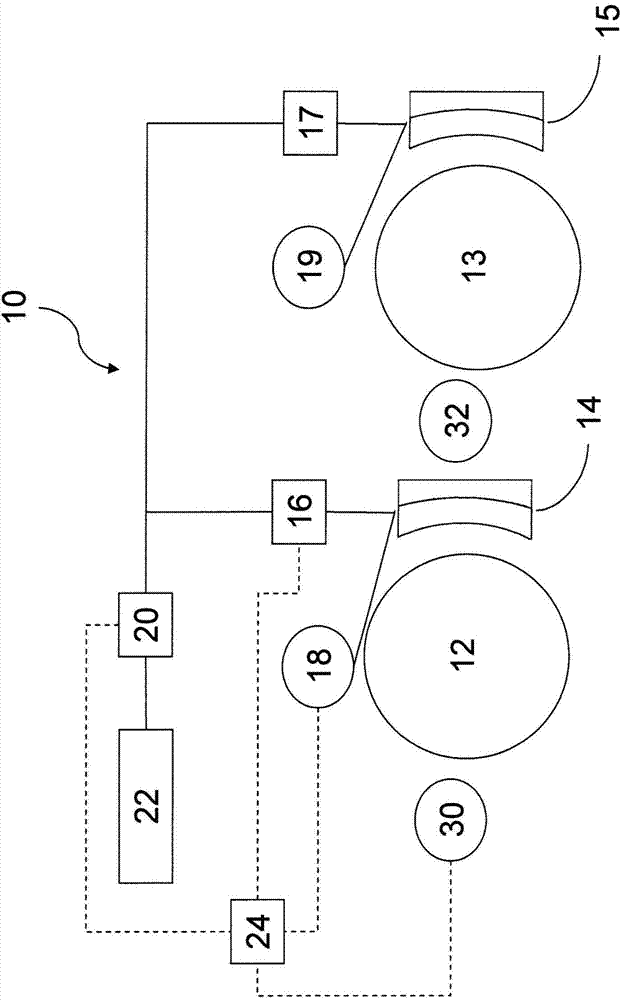
[0020] figure 1 A braking system 10 of a rail vehicle is shown schematically. Mechanical and pneumatic connections and lines are shown by solid lines, while electrical connections or communication channels are shown by dashed lines. For reasons of clarity, the electrical control lines for the components associated with the second vehicle are not shown. Of course, it is analogous to the control lines associated with the first wheel and the components of this wheel. The braking system 10 is provided for braking wheels 12 and 13 of a rail vehicle. In this example it is provided that the wheels 12 and 13 are located on different axles. The first brake pad 14 is assigned to the first wheel 12 . The second brake shoe 15 is assigned to the second wheel 13 . Each of the brake shoes 14, 15 has a brake lining which when the brake shoe 14, 15 with the brake lining is pressed onto the working surface of the corresponding wheel 12, 13, the brake lining The corresponding wheels 12, 13...


PUM


Abstract

The invention relates to a brake control device (24) for a brake system (10) of a rail vehicle, said device being designed to detect strain during a braking process on at least one friction brake device (14, 16; 15, 17) actuated during the braking process, the brake control device (24) being further designed to store wear data based on the detected strain in a memory device. The invention further relates to a brake system (10) for a rail vehicle comprising such a brake control device (24), and to a rail vehicle comprising such a brake system (10) and / or such a brake control device (24). The invention also relates to a method for operating a brake control device (24) for a brake system (10) of a rail vehicle.

Description

technical field [0001] The invention relates to a brake control device for a braking system of a rail vehicle, a braking system for a rail vehicle with such a brake control device, a rail vehicle and a system for operating The invention relates to a method of a brake control device for a brake system of a rail vehicle. Background technique [0002] Modern rail vehicles can have many different types of braking equipment. Pneumatic brake systems are usually present in rail vehicles, which can brake the rail vehicle by pneumatically actuating friction brake elements. Furthermore, there are eg magnetic track brakes and eddy current brakes. Eddy-current brakes brake the vehicle without wear. When actuating the friction brake device, the friction pairs that are in contact with each other are significantly stressed. Such frictional pairs may, for example, comprise the disc of a brake disc and the brake lining of a brake shoe in a disc brake or the lining of a brake shoe and the...

Claims


Application Information

Patent Timeline
Patent Type & Authority Applications(China)
IPC IPC(8): B60T8/17B60T13/66B60T17/22
CPCB60T8/1705B60T17/228B60T13/665B61H13/00
Inventor 马克-格雷戈里·埃尔斯托普夫马尔科·诺克米里亚姆·范德勒希特
Owner KNORR BREMSE SYST FUR SCHIENENFAHRZEUGE GMBH
Why Eureka
Try Eureka