X ray real-time imaging device

A technology of real-time imaging and supporting devices, applied in radiation safety devices, medical science, instruments for radiological diagnosis, etc., can solve vertical and unchangeable problems

Active Publication Date: 2014-05-14
BEIJING EAST WHALE IMAGE TECH
View PDF12 Cites 35 Cited by
  • Summary
  • Abstract
  • Description
  • Claims
  • Application Information

AI Technical Summary

Problems solved by technology

The disadvantage of this device is that the angle between ...

Method used


Image

  • X ray real-time imaging device
  • X ray real-time imaging device
  • X ray real-time imaging device

Examples


Embodiment 1

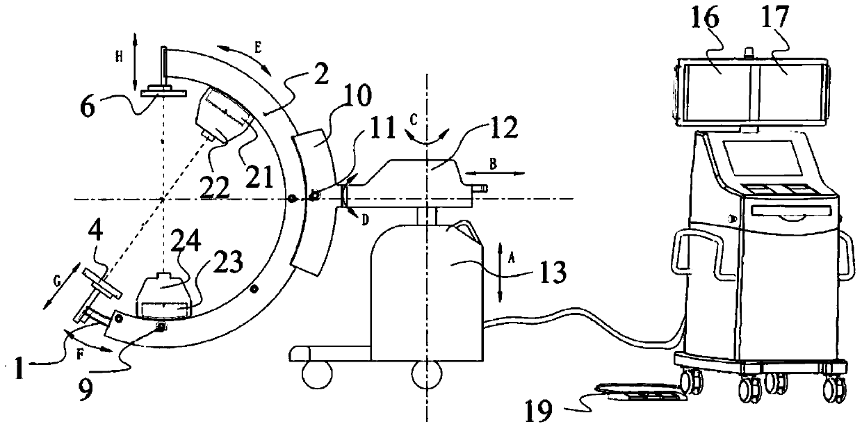
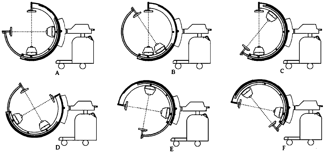
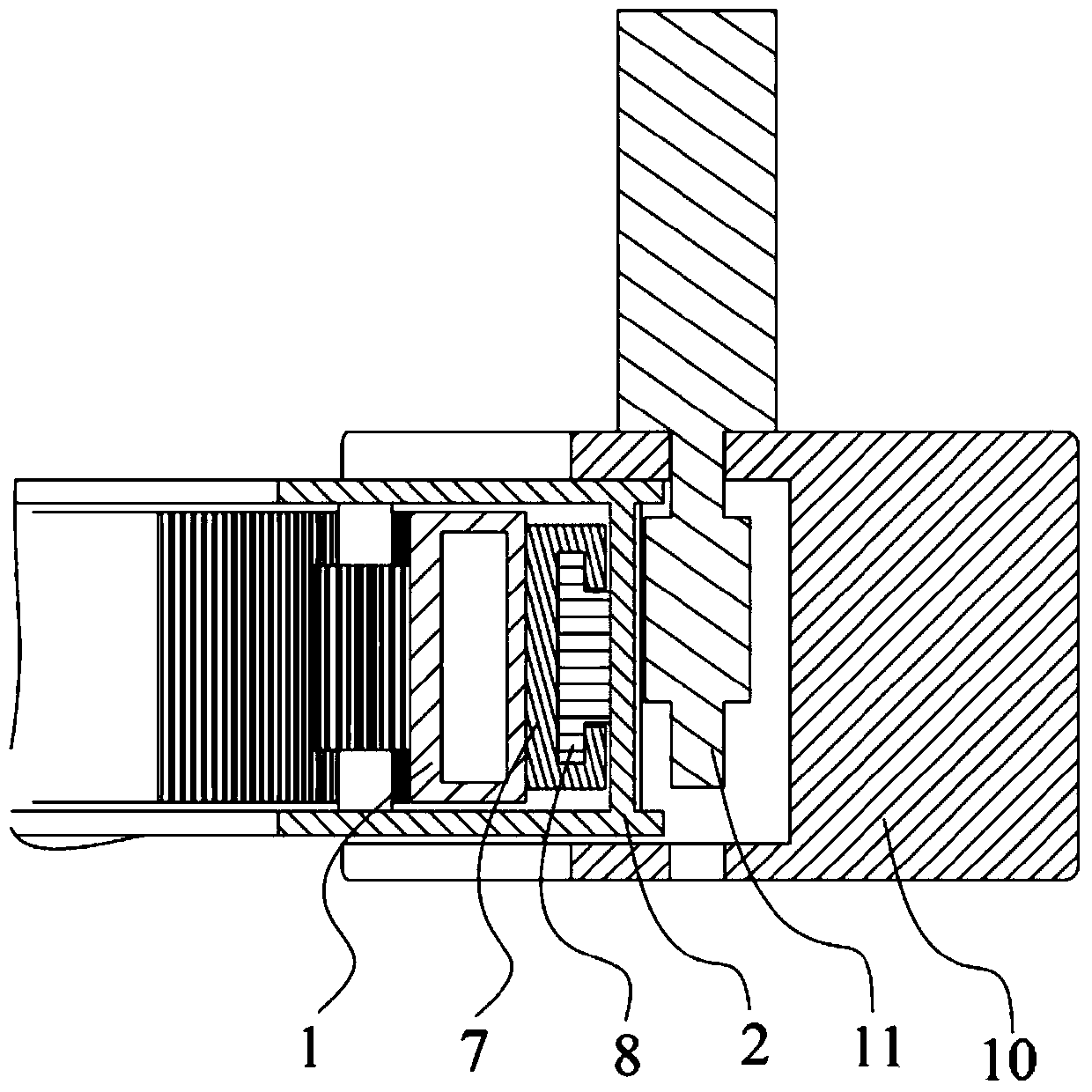
[0027] refer to Figure 1-6 , this embodiment provides an X-ray real-time imaging device, including a first C-arm 1, a second C-arm 2 and a supporting device, the first C-arm 1 is slidably arranged on the second C-arm 2, i.e. figure 1 In the F direction shown in , the second C-shaped arm 2 is slidably arranged on the support device, and the two ends of the first C-shaped arm 1 along the circumferential direction are respectively fixed with first X-ray generating devices. and the first image receiving device 4; the two ends of the second C-shaped arm 2 along the circumferential direction are respectively fixed with a second X-ray generating device and a second image receiving device 6, and the X-ray generating device of the first X-ray generating device The intersection line between the light emitting plane and the X-ray emitting plane of the second X-ray generating device is the axis of rotation, and the first X-ray generating device and the first image receiving device 4 are...


PUM


Abstract

The invention discloses an X ray real-time imaging device which comprises a second C-shaped arm and a first C-shaped arm which is arranged on the second C-shaped arm in a sliding mode. A first X ray generator and a first image receiving device are arranged on the first C-shaped arm so as to form a first imaging device. A second X ray generator and a second image receiving device are arranged on the second C-shaped arm to form a second imaging device. The rotation axis of the first C-shaped arm is identical with that of the second C-shaped arm. According to the X ray real-time imaging device, when the first C-shaped arm slides along the second C-shaped arm, the first imaging device and the second imaging device can form different angles. In addition, as the rotation axis of the first C-shaped arm is identical with that of the second C-shaped arm, the rotation axes of the first imaging device and the second imaging device are identical.

Description

technical field [0001] The invention relates to an X-ray imaging device, in particular to an X-ray real-time imaging device. Background technique [0002] Because the biplane imaging device can position the patient more precisely, help doctors save operation time, reduce exposure dose and maintain a sterile environment and many other advantages, it is widely used in surgery. [0003] The biplane imaging device can be realized by, for example, the device in U.S. Patent No. 4,884,293, which describes a biplane imaging system, wherein one imaging system is fixedly installed on the The system is suspended from ceiling rails. The disadvantage of this device is that the two sets of imaging systems need to be precisely matched during the initial installation, which can easily cause the consequences of different rotation axes of the two sets of systems. [0004] The biplane imaging device can also be realized by, for example, the device in U.S. Patent No. 3,549,885, which describe...

Claims


Application Information

Patent Timeline
IPC IPC(8): A61B6/00A61B6/10
Inventor 朱洵贺兴柏张军
Owner BEIJING EAST WHALE IMAGE TECH
Why Eureka
Try Eureka