Pressure cooling process of segmented reinforcing type parts of hot forming steel plate, and pressing machine servo ejector rod devices

A segmented strengthening and hot forming technology, applied in the field of high-strength steel stamping, can solve problems such as complex structures, achieve uniform processing technology, improve product strength or elongation, and have simple structures

Active Publication Date: 2014-05-14
WUXI LANGXIAN LIGHTWEIGHT TECH CO LTD
View PDF5 Cites 1 Cited by
  • Summary
  • Abstract
  • Description
  • Claims
  • Application Information

AI Technical Summary

Problems solved by technology

[0017] But the defect of this technology is: from the point of view, this method is an improvement to the conventional practice of the existing soft zone technology - heating the mold to 370-700 ° C - in order to reduce the wear of the mold in production after heating, Or reduce the heating equipment, but still need to heat the mold, which belongs to the temperature control technology of the cooling medium
In terms of mold structure, this technology requires a heating device inside the active punch and die, so the structure is complicated

Method used


Image

  • Pressure cooling process of segmented reinforcing type parts of hot forming steel plate, and pressing machine servo ejector rod devices
  • Pressure cooling process of segmented reinforcing type parts of hot forming steel plate, and pressing machine servo ejector rod devices
  • Pressure cooling process of segmented reinforcing type parts of hot forming steel plate, and pressing machine servo ejector rod devices

Examples


Embodiment 1

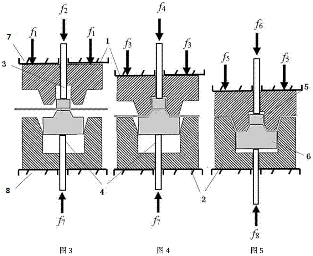
[0061] Such as Figure 3-Figure 5 As shown, the workpiece is 1.8mm thick, 150mm wide, and 1000mm long. The workpiece product requirement is f6 and the corresponding product area is HS400 soft area, and the rest are hard area HS1150. The concrete preparation process schematic diagram of this method, wherein:

[0062] figure 1 In its original state, according to figure 1 It can be seen that the device for realizing this method includes: upper mold 1, lower mold 2, upper servo ejector pin 3 of the press, lower servo ejector pin 4 of the press, upper mold pressing core 5, lower mold pressing core 6, upper workbench of the press ( Slider) 7, workbench 8 under the press.

[0063] The upper mold 1 covers the range of HS1150 in the hard area of ​​the product, and the material is high-quality mold steel SKD61;

[0064] The upper mold pressing material core 5 covers the product soft zone HS400 range, and the material is high-quality mold steel SKD61;

[0065] The lower mold pressi...

Embodiment 2

[0076] Such as Figure 3-Figure 5 As shown, the workpiece is 1.8mm thick, 150mm wide, and 1000mm long. The product requirement of the workpiece is that the product area corresponding to f6 is HS400 soft area, f8 is soft area HS700 except for f6 area, and the rest areas of the product are hard area HS1150.

[0077] This method realizes the device such as figure 1 shown, where:

[0078] The upper mold 1 covers all areas of the product soft area HS700 and hard area HS1150, and the material is high-quality die steel SKD61;

[0079] The upper mold pressing material core 5 covers all areas of the soft area HS700 of the product, and the material is high-quality mold steel SKD61;

[0080] The lower mold pressing material core 6 covers all areas of the product soft zone HS400 and soft zone HS700, and the material is high-quality mold steel SKD61;

[0081] The lower mold 2 covers all areas of the hard area HS1150 of the product, and the material is high-quality mold steel SKD61;

...


PUM

PropertyMeasurementUnit
strengthaaaaaaaaaa
plasticityaaaaaaaaaa

Abstract

The invention discloses a pressure cooling process of segmented reinforcing type parts of a hot forming steel plate, and pressing machine servo ejector rod devices. Through the independent pressing machine servo ejector rod devices, the magnitude of loading force borne by a workpiece and/or force bearing and pressure keeping time for the workpiece are adjusted, and therefore the cooling speed of each sub-area of the workpiece is controlled, different types of material mechanical performance of the sub-areas of the workpiece are obtained. Required material characteristics can be achieved for any area according to the design requirements, no additional die heating device needs to be arranged, and production cost and procedure complexity are greatly reduced.

Description

technical field [0001] The invention relates to a method in the technical field of high-strength steel stamping, in particular to a pressure cooling process for segmentally strengthened hot-formed steel plate parts with a strength of about 1500 MP and a press ejector pin servo device. Background technique [0002] As a new type of ultra-high-strength hot-formed steel plate, automotive boron steel plate provides the possibility for segmental strengthening technology—the same part can adopt different heat treatment processes in different regions of the part according to the needs of automobile design, so as to obtain different strength and plasticity. The production process of the soft zone technology for hot-formed boron steel materials is divided into 4 stages: [0003] 1) Heating: heating the boron steel plate to the temperature required for heat treatment; [0004] 2) Transmission: transfer the boron steel plate to the die to be stamped; [0005] 3) Forming: Stamping an...

Claims


Application Information

Patent Timeline
Patent Type & Authority Applications(China)
IPC IPC(8): B21D22/02B21D37/16
Inventor 陈扬
Owner WUXI LANGXIAN LIGHTWEIGHT TECH CO LTD
Why Eureka
Try Eureka