Accelerator anti-misstepping device

An anti-mistake and accelerator technology, which is applied to the layout of the power unit control mechanism, transportation and packaging, and vehicle components, can solve the problems of heavy refitting workload, large changes, and high costs, and achieve traffic accident avoidance, small overall structure, and The effect of modifying small

Inactive Publication Date: 2016-08-31
CHONGQING JIAOTONG UNIVERSITY
View PDF8 Cites 0 Cited by
  • Summary
  • Abstract
  • Description
  • Claims
  • Application Information

AI Technical Summary

Problems solved by technology

The car is one of the main means of transportation. At present, the brake and accelerator of the car are controlled by the right foot. The two are very close to each other. When the driver is in a nervous state, he may mistake the accelerator for the brake. cause an accident
In the existing anti-acceleration system for automobiles, there are mainly three types: the first is to change the structure of the existing brake, and the left and right feet are operated separately, the left foot controls the accelerator, and the right foot controls the brake. The disadvantage is that in an emergency state, it is easy to make mistakes in the power of the left and right feet; the second is to detect the speed through some electronic components and light control components, and design an emergency braking device. The disadvantage is that the cost is relatively high. The original device has been changed a lot; the third is to use the collision sensing device to obtain the signal of false stepping, and then the solenoid valve cuts off the oil circuit and uses the electric winch to pull the brake pedal to achieve braking. The disadvantage is that the modification workload is large and the winch pulls the pedal. The speed is slow, and traffic accidents often have already occurred when the collision sensing device is activated, it is difficult to reduce the damage caused by the accident

Method used


Image

  • Accelerator anti-misstepping device

Examples


Embodiment Construction

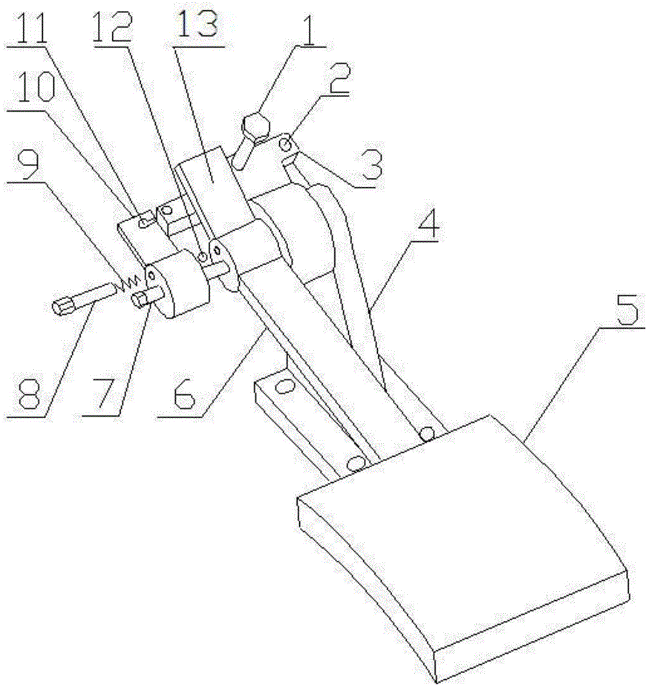
[0015] figure 1 It is a structural schematic diagram of the present invention, as shown in the figure, the throttle anti-misstepping device of the present invention includes a mounting seat, a pedal assembly, a throttle rod 10 and a locking mechanism; the pedal assembly and the throttle rod 10 are aligned along the same hinge Hinged to the mounting seat; the locking mechanism is connected between the pedal assembly and the accelerator rod to control the synchronous rotation of the pedal assembly and the accelerator rod when the accelerator is not stepped on by mistake, and relative rotation occurs when the accelerator is stepped on by mistake. In the case of an electronic accelerator system, the sensing part of the pedal 5 position sensor in the electronic accelerator can be set on the accelerator rod 10, so that the pedal 5 position sensor can collect the position of the accelerator rod 10, and then the accelerator can be prevented from accidentally stepping on the electronic ...


PUM


Abstract

The invention discloses an accelerator mistaken pedaling preventing device which comprises an installation seat, a pedal rod component, an accelerator pulling rod and a locking mechanism. The pedal rod component and the accelerator pulling rod are hinged to the installation seat along the same hinge shaft, and the locking mechanism is connected between the pedal rod component and the accelerator pulling rod and used for controlling synchronous rotation of the pedal rod component and the accelerator pulling rod when an accelerator is not mistakenly pedaled and relative rotation of the pedal rod component and the accelerator pulling rod when the accelerator is mistakenly pedaled. According to the accelerator mistaken pedaling preventing device, the locking mechanism is used for controlling linkage or relative rotation of the pedal rod component and the accelerator pulling rod, so that the accelerator pulling rod is prevented from continuing to act after the pedal rod component is mistakenly pedaled, and traffic accidents due to mistaken pedaling of the accelerator can be effectively avoided. The accelerator mistaken pedaling preventing device is safe, reliable, small in overall structure, little in modification of an automobile, capable of not changing the original driving operation habits of the automobile in use, and capable of achieving install-and-play.

Description

technical field [0001] The invention relates to an automobile part, in particular to an anti-misstepping accelerator device. Background technique [0002] With the development of science and technology, the continuous improvement of people's living standards, and the rapid change of transportation means, traffic safety issues are getting more and more attention. The car is one of the main means of transportation. At present, the brake and accelerator of the car are controlled by the right foot. The two are very close to each other. When the driver is in a nervous state, he may mistake the accelerator for the brake. cause an accident. In the existing anti-acceleration system for automobiles, there are mainly three types: the first is to change the structure of the existing brake, and the left and right feet are operated separately, the left foot controls the accelerator, and the right foot controls the brake. The disadvantage is that in an emergency state, it is easy to mak...

Claims


Application Information

Patent Timeline
Patent Type & Authority Patents(China)
IPC IPC(8): B60K26/02
Inventor 邓涛李亚南黄希光卢任之林椿松李小静
Owner CHONGQING JIAOTONG UNIVERSITY
Why Eureka
Try Eureka