A kind of oil pipe joint

A technology for oil pipe joints and pipelines, applied in the hydraulic field, can solve problems such as danger and metal leakage, and achieve the effect of improving the effect.

Active Publication Date: 2016-03-09
NANTONG AMC MACHINERY
View PDF9 Cites 1 Cited by
  • Summary
  • Abstract
  • Description
  • Claims
  • Application Information

AI Technical Summary

Problems solved by technology

[0002] Traditional oil pipe joints are sealed by the principle of compression bolts or expansion bolts, but this rigid compression sealing mechanism will leak due to the plastic deformation of the metal after a long period of use, causing danger

Method used


Image

  • A kind of oil pipe joint
  • A kind of oil pipe joint

Examples


Embodiment Construction

[0014] Further description will be given below in conjunction with the accompanying drawings

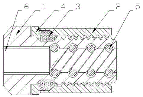
[0015] An oil pipe joint, comprising a joint main body 1 and a locking sleeve 2, the joint main body 1 is a hollow cylinder, an equipment connection part 6 is provided at one end of the hollow cylinder in the axial direction, and a pipe is provided at the other axial end of the hollow cylinder connecting part;

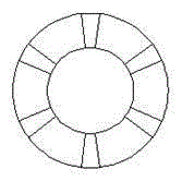
[0016] The outer wall of the hollow cylinder of the pipe connection part is provided with threads, and the locking sleeve 2 is sleeved on the outer wall of the hollow body through threads. The inner wall of the hollow body of the pipe connection part is provided with a spiral groove, and a coil spring 5 is embedded in the spiral groove. A plurality of linear grooves are arranged on the wall surface of the hollow main body of the connection part;

[0017] The equipment connection part 6 is provided with threads connected with the equipment;

[0018] The end of the locking sl...


PUM


Abstract

The invention relates to an oil pipe joint, comprising a joint main body and a locking sleeve. The joint main body is a hollow cylinder, an equipment connection part is arranged at one axial end of the hollow cylinder, and a The pipe connection part; the outer wall of the hollow cylinder of the pipe connection part is provided with threads, the locking sleeve is sleeved on the outer wall of the hollow body through threads, and the inner wall of the hollow body of the pipe connection part is provided with a spiral groove. A coil spring is inlaid in the spiral groove, and several linear grooves are arranged on the wall surface of the hollow main body of the pipe connection part; the equipment connection part is set according to the specific working conditions of the equipment; the present invention adds a coil spring to the inner wall of the expansion plug, It improves the tightening effect, and at the same time prevents the plastic deformation of the joint metal from affecting the sealing effect under long-term compression.

Description

technical field [0001] The invention relates to an oil pipe joint, which belongs to the field of hydraulic pressure. Background technique [0002] The traditional oil pipe joint is sealed by the principle of compression bolt or expansion bolt, but this rigid compression sealing mechanism will leak due to the plastic deformation of the metal after a long time of use, causing danger. Contents of the invention [0003] The purpose of the present invention is to provide an oil pipe joint which can prevent plastic deformation of the metal at the joint to a certain extent. [0004] The present invention is realized by following method: [0005] An oil pipe joint, comprising a joint main body and a locking sleeve, the joint main body is a hollow cylinder, an equipment connection part is provided at one axial end of the hollow cylinder, and a pipeline connection part is provided at the other axial end of the hollow cylinder ; [0006] The outer wall of the hollow cylinder of th...

Claims


Application Information

Patent Timeline
Patent Type & Authority Patents(China)
IPC IPC(8): F16L15/04
CPCF16L19/0206F16L19/0218
Inventor 戚顺平
Owner NANTONG AMC MACHINERY
Why Eureka
Try Eureka