
Gas appliance

A technology of gas appliances and gas cylinders, which is applied in the direction of heating fuel, electrical components, household appliances, etc., which can solve the problem of difficult to provide charging power for portable communication terminals, difficult to maintain the temperature range of thermal power generation components, and difficult to maintain high temperature terminals and low temperature terminal temperature difference

Inactive Publication Date: 2014-05-14
岩谷气具(珠海)有限公司
View PDF6 Cites 5 Cited by
  • Summary
  • Abstract
  • Description
  • Claims
  • Application Information

AI Technical Summary

Problems solved by technology

[0005] However, the thermal power generation element disclosed in Patent Document 1 is tightly and fixedly connected to the side of the burner, that is, at the gas outlet. In addition, the temperature difference between the high temperature terminal and the low temperature terminal of the thermal power generation element is only the gas (combustion) temperature and The temperature difference between the room temperature, so it is difficult for such a thermoelectric element to maintain a sufficient temperature difference between the high-temperature terminal and the low-temperature terminal, and it is also difficult to maintain a temperature range that is favorable for the thermoelectric element to generate electricity
Therefore, in Patent Document 1, although it is possible to generate thermal electromotive force (thermal power) sufficient to start the timer, it is difficult to provide sufficient electric power to charge the portable communication terminal.

Method used


Image

  • Gas appliance
  • Gas appliance
  • Gas appliance

Examples


Embodiment 1

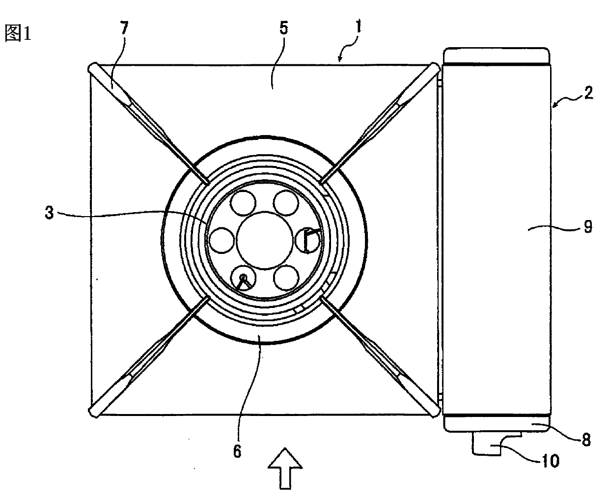
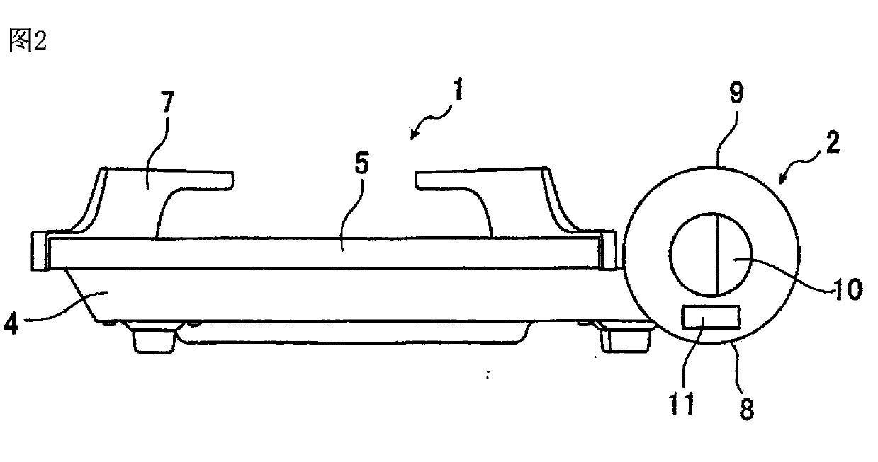
[0025] figure 1 It is a plan view of the overall structure of the gas appliance in Embodiment 1 of the present invention, figure 2 yes figure 1 Side view of the indicated gas appliance in the direction of the arrow.

[0026] Such as figure 1 and figure 2 As shown, the gas appliance of Embodiment 1 is composed of a body part 1 and a gas cylinder mounting part 2. The body part 1 has a burner 3, a body lower part 4 supporting the burner 3, an upper cover 5 arranged on the body lower part and an upper cover arranged on the upper part. The liquid receiving tray 6 and the furnace frame 7 on the cover 5, the gas cylinder installation part 2 has a container support body 8, a container cover 9 that can be opened and closed on the container support body 8, and a switch that is arranged at the end of the container support body 8 The knob 10 and the output terminal 11 provided on the lower side of the switch knob 10 .

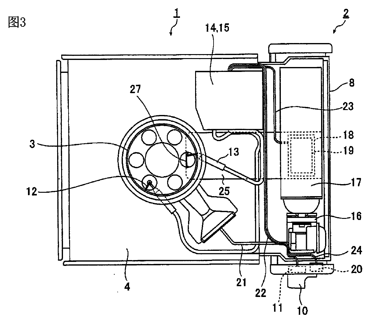
[0027] image 3 From figure 1 and figure 2 The internal pl...

Embodiment 2

[0065] Figure 6It is a partial sectional view in the side direction of the gas appliance according to Embodiment 2 of the present invention. The difference in structure between Embodiment 2 and Embodiment 1 is that the thermoelectric conversion element 19 is not arranged under the liquefied gas bottle 17, and the heat conduction plate 118 on the side of the liquefied gas bottle extends from the liquefied gas bottle 17 to the burner side by a certain distance. The burner-side end is provided with a thermoelectric conversion element 19 , and the thermoelectric conversion element 19 is sandwiched between the end of the liquefied gas bottle-side heat conducting plate 118 near the burner and the end of the burner-side cooling plate 125 near the gas bottle.

[0066] Compared with Example 1, although the cooling efficiency of the gas appliance in Example 2 is reduced, considering that the heating efficiency of gas combustion is improved, it can supply power to the connected electric...


PUM


Abstract

The invention provides a gas appliance capable of generating electricity when performing heating, wherein the electricity is much enough to charge a portable communication terminal. A heat collecting portion 26 is heated by combustion heat generated by a combustor 3. A high-temperature terminal H of a thermoelectric converting element 19 is heated through a combustor-side heat-dissipating plate 25 equipped with the heat collecting portion 26. Liquefied gas and a liquefied gas bottle 17 are both cooled by evaporation heat of the liquefied gas generated by supplying gas to the combustor 3. A low-temperature terminal L of the thermoelectric converting element 19 is cooled through a liquefied-gas-bottle-side heat-dissipating plate 18 tightly connected with the liquefied gas bottle 17. Specific temperature difference is generated in a specific temperature zone between the high-temperature terminal H of the thermoelectric converting element 19 and the low-temperature terminal L of the thermoelectric converting element 19 such that the thermoelectric converting element 19 generates electricity.

Description

technical field [0001] The invention relates to a gas appliance which burns gas supplied by a liquefied gas bottle on a burner. Background technique [0002] For a long time, in fields such as catering, some card-type gas appliances such as LPG side stoves (カセットコンロ) that can be used indoors and outdoors are often used. In recent years, the importance of these card-type gas appliances as a heating and cooking tool that can be used in disasters or emergency times has been re-recognized by people. [0003] In addition, in times of disaster or emergency, it is desirable to use these card-type gas appliances to charge communication devices such as portable communication terminals represented by mobile phones. [0004] In the patent document 1 of the Publication No. Hei 5-8243, an invention of a petroleum gas side stove is disclosed, which has a thermoelectric power generation element and a timer, and generates electricity through the combustion heat generated by burning gas in t...

Claims


Application Information

Patent Timeline
Patent Type & Authority Applications(China)
IPC IPC(8): F24C3/00H02N11/00
Inventor 平山丰之
Owner 岩谷气具(珠海)有限公司
Learn More