Parameter setting method and system of on-board unit and apparatuses
An on-board unit and parameter setting technology, applied in ticketing equipment, instruments, etc., can solve the problems of OBU and RSU communication failure, collision rod, low flexibility, etc., to ensure the success rate of communication and the effect of flexible installation
- Summary
- Abstract
- Description
- Claims
- Application Information
AI Technical Summary
Problems solved by technology
Method used
Image

Examples
Embodiment 1
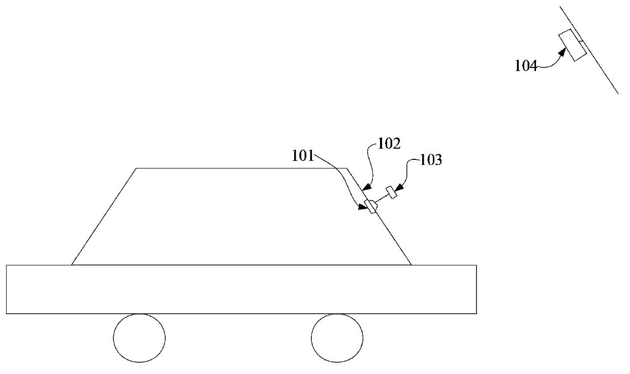
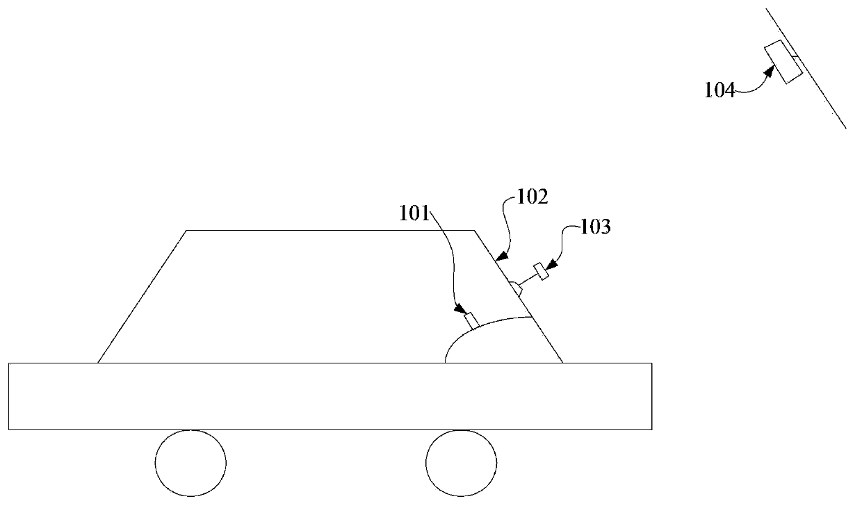
[0032] Please refer to figure 1 , the OBU101 is installed on the inside of the front windshield 102, and the calibration device 103 is installed on the outside of the front windshield 102 through a suction cup. In order to simulate the RSU104, the calibration device 103 makes the connection line between the OBU101 and the calibration device 103 perpendicular to the front windshield 102 Of course, in other embodiments, the connection line between the OBU 101 and the calibrator 103 is not necessarily perpendicular to the front windshield 102 .
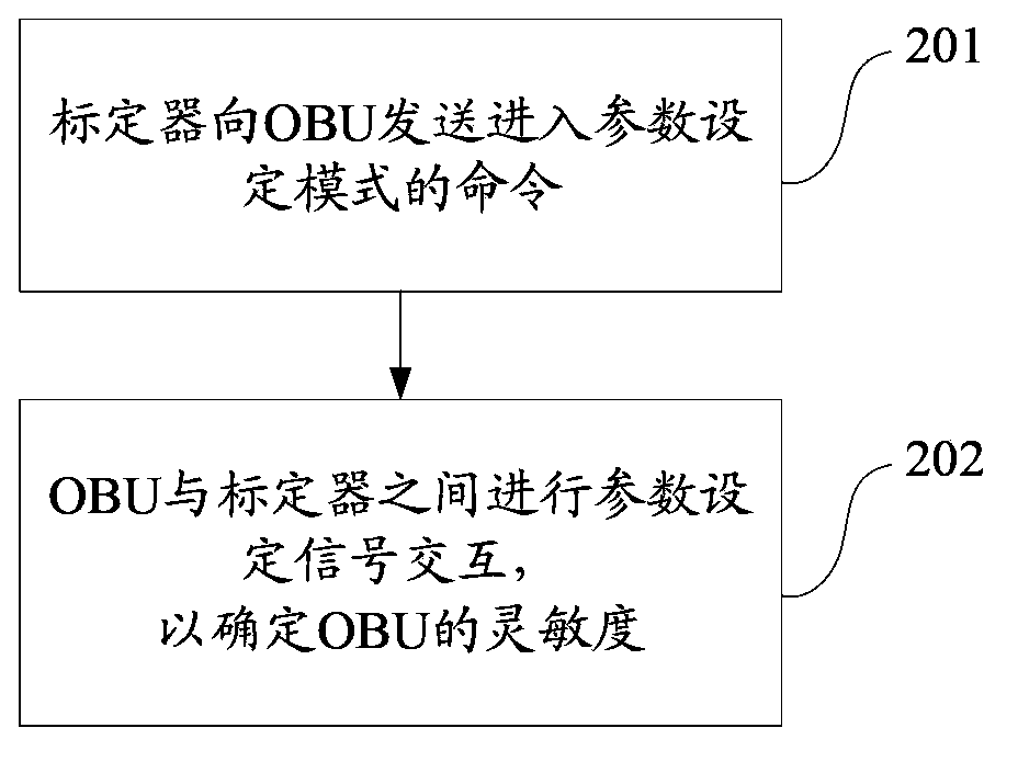
[0033] Based on the position setting of the OBU 101 and the calibrator 103, the parameter setting method of the OBU 101 in this embodiment mainly includes the following steps: figure 2 Flow shown:
[0034] Step 201, turn on the calibrator 103, and the calibrator 103 sends a command for triggering the OBU101 to enter the parameter setting mode to the OBU101. Specifically, because this step is to make the OBU101 enter the parameter setti...
Embodiment 2
[0041] The main difference between this embodiment and the first embodiment is that: in the above step 202, the parameter setting signal interaction process between the OBU 101 and the calibrator 103 and the determination process of the sensitivity of the OBU 101 may be as follows:
[0042] After the OBU101 enters the parameter setting mode, the initial setting range of the sensitivity of the OBU101 (for example, between -70dbm (the highest sensitivity) to -40dbm (the lowest sensitivity)) is obtained, and the initial setting range is at the maximum setting value of the sensitivity of the OBU101 (ie -70dbm) and the minimum set value (ie -40dbm);
[0043] OBU101 uses the middle value of the initial setting range (ie -55dbm) as the sensitivity of OBU101 for parameter setting signal interaction. When the interaction fails, the middle value (ie -55dbm) is used as the minimum value and the maximum set value (ie- 70dbm) to reset the set range for the maximum value (i.e. between -70db...
Embodiment 3
[0045] The main difference between this embodiment and the first embodiment is that: in the above step 202, the parameter setting signal interaction process between the OBU 101 and the calibrator 103 and the determination process of the sensitivity of the OBU 101 may be as follows:
[0046] After the OBU101 enters the parameter setting mode, a list of setting values of the sensitivity of the OBU101 is obtained. Specifically, the list lists the setting values of the sensitivity of the multi-level OBU101 (for example, the first level is -60dbm, and the second level is -50dbm). , the third gear is -40dbm, the fourth gear is -30dbm, etc.);
[0047] OBU101 uses an initial value indicated by the list (such as -50dbm) as the sensitivity of OBU101 for parameter setting signal interaction. When the interaction is successful, the next setting value (-40dbm) smaller than the initial value (ie -50dbm) is used as the The sensitivity of OBU101 performs parameter setting signal interacti...
PUM
 Abstract
Description
Claims
Application Information
 - Generate Ideas
- Intellectual Property
- Life Sciences
- Materials
- Tech Scout
- Unparalleled Data Quality
- Higher Quality Content
- 60% Fewer Hallucinations
Browse by: Latest US Patents, China's latest patents, Technical Efficacy Thesaurus, Application Domain, Technology Topic, Popular Technical Reports.
© 2025 PatSnap. All rights reserved.Legal|Privacy policy|Modern Slavery Act Transparency Statement|Sitemap|About US| Contact US: help@patsnap.com