Eureka AIR delivers breakthrough ideas for toughest innovation challenges, trusted by R&D personnel around the world.

Wireless transceiving device with frequency band matching adjusting function and adjusting method of wireless transceiving device

A technology of a wireless transceiver device and an adjustment method, applied to electrical components, transmission systems, etc., can solve the problems of radio frequency signal loss, reduction of the area of ​​the wireless transceiver device 10 and production cost, etc.

Active Publication Date: 2014-05-14
AIROHA TECHNOLOGY CORPORATION
View PDF6 Cites 0 Cited by
  • Summary
  • Abstract
  • Description
  • Claims
  • Application Information

AI Technical Summary

Problems solved by technology

However, the wireless transceiver 10 needs to be provided with a plurality of radio frequency switch units 12, a plurality of transmitting matching units 13 and a plurality of receiving matching units 14, so that the area and manufacturing cost of the wireless transmitting and receiving device 10 cannot be effectively reduced.
In addition, in the process of transmitting or receiving radio frequency signals, radio frequency signals will pass through a radio frequency switch unit 12, resulting in loss of radio frequency signals

Method used


Image

  • Wireless transceiving device with frequency band matching adjusting function and adjusting method of wireless transceiving device
  • Wireless transceiving device with frequency band matching adjusting function and adjusting method of wireless transceiving device
  • Wireless transceiving device with frequency band matching adjusting function and adjusting method of wireless transceiving device

Examples


Embodiment Construction

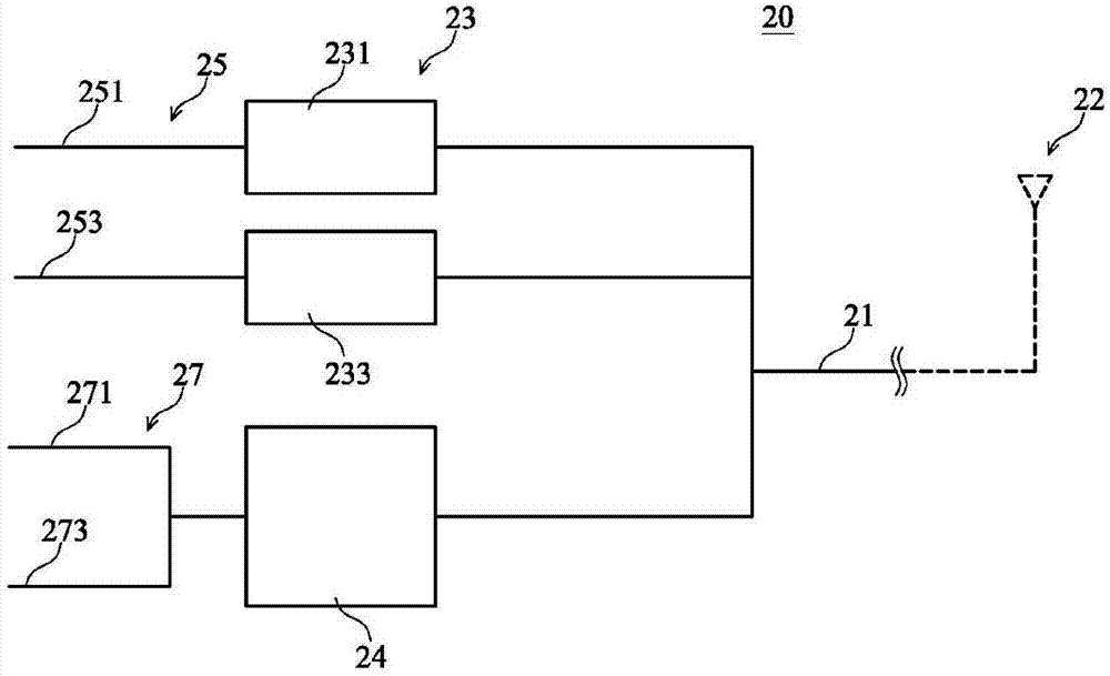
[0070] Please refer to figure 2 , is a schematic structural diagram of an embodiment of a wireless transceiver device with a frequency band matching adjustment function according to the present invention. As shown in the figure, the wireless transceiver device 20 according to the embodiment of the present invention includes a radio frequency signal transceiver terminal 21, a plurality of frequency band matching circuits 23, a frequency band matching adjustment circuit 24, a plurality of transmitting lines 25 and a plurality of receiving lines 27, The frequency band matching adjustment circuit 24 is connected to multiple receiving lines 27 or multiple transmitting lines 25 , while the multiple frequency band matching circuits 23 are respectively connected to multiple transmitting lines 25 or multiple receiving lines 27 not connected to the frequency band matching adjustment circuit 24 . In this embodiment, the receiving line 27 is connected to the radio frequency signal transc...


PUM


Abstract

The invention provides a wireless transceiving device with the frequency band matching adjusting function and an adjusting method of the wireless transceiving device. The wireless transceiving device mainly comprises a plurality of transmitting circuits, a plurality of receiving circuits, a frequency band matching adjusting circuit and a radio-frequency signal transceiving end, wherein the transmitting circuits and / or the receiving circuits are connected with the radio-frequency signal transceiving end through the frequency band matching adjusting circuit. When / before radio-frequency signals are transmitted or received, the impedance of the frequency band matching adjusting circuit can be adjusted according to the frequency band of the radio-frequenyc signals, the frequency band, relative to received or transmitted radio-frequency signals, of the frequency band matching adjusting circuit is made to be high impedance or low impedance, and therefore the loss caused when the radio-frequency signals are received or transmitted is reduced.

Description

technical field [0001] The invention relates to a wireless transceiver device with a frequency band matching adjustment function and an adjustment method thereof, which can reduce the loss of radio frequency signals during reception or transmission. Background technique [0002] Please refer to figure 1 , is a schematic block diagram of an existing wireless transceiver. The wireless transceiver device (transceiver) 10 is used to transmit and receive wireless signals, and includes an antenna unit 11, a plurality of radio frequency switch units 12, a plurality of transmitting matching units 13, a plurality of receiving matching units 14, a plurality of transmitting lines 15 and a plurality of A receiving line 17, wherein the antenna unit 11 is connected to the transmitting line 15 through a part of the radio frequency switch unit 12 and the transmitting matching unit 13, and is connected to the receiving line 17 through other radio frequency switching units 12 and the receivi...

Claims


Application Information

Patent Timeline
Patent Type & Authority Applications(China)
IPC IPC(8): H04B1/40
Inventor 郭秉捷李道一
Owner AIROHA TECHNOLOGY CORPORATION
Why Eureka
Eureka Blog
Learn More