Bending Stamping Die

A stamping die and bending technology, applied in the field of die, can solve the problems of low production efficiency, many bending operation procedures, and the production method cannot meet the needs, and achieve the effect of high production efficiency and simple operation.

Active Publication Date: 2015-12-02
CRRC TANGSHAN CO LTD
View PDF4 Cites 0 Cited by
  • Summary
  • Abstract
  • Description
  • Claims
  • Application Information

AI Technical Summary

Problems solved by technology

[0003] There are many bending operations for the above-mentioned workpieces, and the production efficiency is low. For workpieces with large batches, this production method cannot meet the needs

Method used


Image

  • Bending Stamping Die
  • Bending Stamping Die
  • Bending Stamping Die

Examples


Embodiment Construction

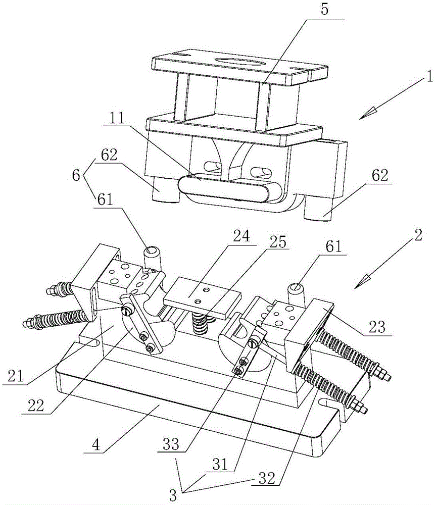
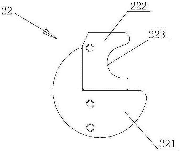
[0014] Embodiments of the present invention provide a bending stamping die, such as figure 2 and image 3 As shown, the bending stamping die includes a punch 1 and a die 2 corresponding to the punch 1, through the cooperation of the punch 1 and the die 2, the bending of the workpiece is completed; wherein the die 2 includes a die body 21 And the rotary block 22 embedded on the concave mold body 21 that can rotate relative to the concave mold body 21, the rotary block 22 is provided with the molding surface of the bending position of the workpiece; The punch 1 can push the rotary block 22 to rotate, and the forming surface of the rotary block 22 rotates and the die body 21 forms a cavity for bending and stamping the workpiece. At this time, the die body 11 of the punch 1 gradually enters the cavity of the die 2 In the model cavity, the state after the mating of the punch 1 and the die 2 is as follows: Figure 5 As shown, the workpiece in the concave mold cavity is stamped an...


PUM


Abstract

The invention relates to a bending and stamping die which comprises a male die and a female die corresponding to the male die, wherein the female die comprises a female die body and a rotating block which is embedded on the female die body and can rotate relative to the body of the female die, a forming surface with a workpiece bending position is arranged on the rotating block; during the folding process of the male die and the female die, the male die can push the rotating block to rotate, the forming surface of the rotating block rotates to form a female die cavity for workpiece bending and stamping with the body of the female die. In the bending and stamping die provided by the invention, through the arrangement of the rotatable rotating block on the female die, during the matching process of the male die and the female die, the female die cavity is formed on the female die through the rotating of the rotating block, the bending is performed on the workpieces at the same time, one-step bending and forming to workpieces with bending angles smaller than 90 degrees can be achieved, the operation is simple and the production efficiency is high.

Description

technical field [0001] The invention relates to mold technology, in particular to a bending stamping mold. Background technique [0002] In the prior art, when using molds to bend materials, for bending with high precision requirements and an included angle of less than 90 degrees (such as figure 1 As shown in the workpiece, the bending angles on both sides are less than 90 degrees), the bending of this kind of workpiece is usually divided into two steps: first, the material is bent into a right-angled piece with the first set of molds; the second step is to bend the material into a The right-angled workpiece is then bent to the final required angle with a second set of molds. [0003] There are many bending operation procedures for the above-mentioned workpieces, and the production efficiency is low. For workpieces with large batches, this production method cannot meet the needs. Contents of the invention [0004] The invention provides a bending stamping die, which can...

Claims


Application Information

Patent Timeline
Patent Type & Authority Patents(China)
IPC IPC(8): B21D37/10
Inventor 左淑莉杨永勤张海燕尹叶红
Owner CRRC TANGSHAN CO LTD
Why Eureka
Try Eureka