

Injection molding machine and injection molding method
An injection molding machine and molding material technology, applied in the direction of coating, can solve the problems of poor heating efficiency of molding materials, and achieve the effect of good heating efficiency
- Summary
- Abstract
- Description
- Claims
- Application Information
AI Technical Summary
Problems solved by technology
Method used
Image


Examples
no. 1 Embodiment approach
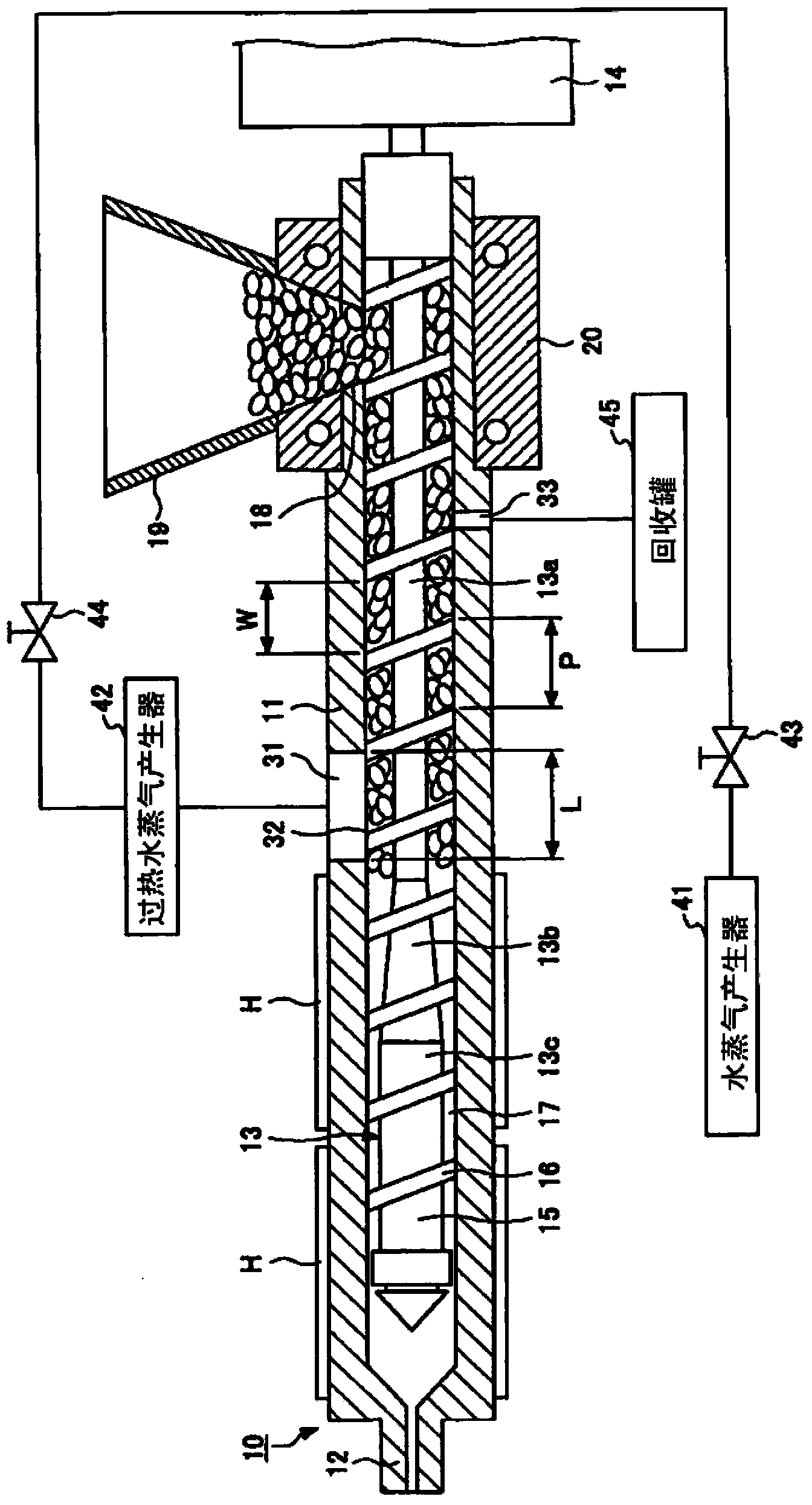
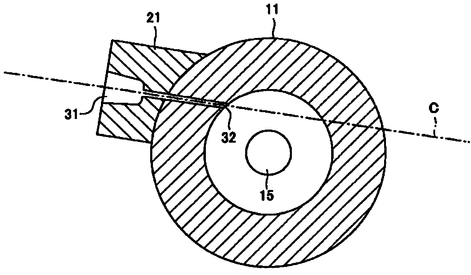
[0031] figure 1 It is a figure which shows the injection molding machine of 1st Embodiment of this invention. exist figure 1 in, omit figure 2 An illustration of the nozzle block 21 shown. figure 2 It is a cross-sectional view of the cylinder in the injection molding machine according to the first embodiment of the present invention, and is a cross-sectional view perpendicular to the axial direction of the cylinder. exist figure 2 In, for the convenience of explanation, omit figure 1 An illustration of the helical airfoil 16 is shown. image 3 It is a figure which shows the supply port of the heat medium formed in the cylinder inner wall in the injection molding machine concerning 1st Embodiment of this invention.
[0032] The injection molding machine 10 includes a cylinder 11 into which a molding material (for example, resin pellets) is supplied, an injection nozzle 12 provided at the front end of the cylinder 11, a screw 13 arranged rotatably and freely advancing a...
no. 2 Embodiment approach
[0066] In the above-described first embodiment, the high-temperature heat medium discharged from the cylinder 11 is recovered to the recovery tank 45 and cooled in the recovery tank 45 .
[0067] On the other hand, the present embodiment is different from the first embodiment in that a recirculation portion is provided to return at least part of the heat medium discharged from the cylinder 11 to the heater for heating the heat medium in order to improve thermal efficiency. Hereinafter, differences will be mainly described.
[0068] Figure 4 It is a figure which shows the injection molding machine of 2nd Embodiment of this invention. Such as Figure 4 As shown, the injection molding machine 110 may include an ejector (Ejector) 50 that returns at least part of the heat medium discharged from the cylinder 11 to the superheated steam generator 42 serving as a heater. The injector 50 corresponds to a recirculation part. The ejector 50 can return at least a part of the heat med...
no. 3 Embodiment approach
[0077] In the above-described first embodiment, the high-temperature heat medium discharged from the cylinder 11 is recovered to the recovery tank 45 and cooled in the recovery tank 45 .
[0078] On the other hand, the present embodiment is different from the first embodiment in that a heat exchange unit for heating the heat medium supplied into the cylinder 11 with the heat medium discharged from the cylinder 11 is provided in order to improve thermal efficiency. Hereinafter, differences will be mainly described.
[0079] Figure 5 It is a figure which shows the injection molding machine of 3rd Embodiment of this invention. Such as Figure 5 As shown, the injection molding machine 210 may include a heat exchange unit 60 that heats the heat medium supplied into the cylinder 11 with the heat medium discharged from the cylinder 11 . Since the heat of the heat medium discharged from the cylinder 11 contributes to the heating of the resin, thermal efficiency is high, and energy...
PUM
 Abstract
Description
Claims
Application Information