Steel arch assembling machine

A technology of steel arch frame and assembly machine, which is applied in the direction of pillars/brackets, mining equipment, earthwork drilling and mining, etc. It can solve the problems of slow splicing speed and cannot meet the requirements of tunnel boring machine's driving speed, so as to prevent vibration damage and be convenient and fast The effect of arch assembly and impact reduction

Active Publication Date: 2014-05-21
CHINA RAILWAY ENGINEERING EQUIPMENT GROUP CO LTD
View PDF9 Cites 10 Cited by
  • Summary
  • Abstract
  • Description
  • Claims
  • Application Information

AI Technical Summary

Problems solved by technology

[0004] The technical problem to be solved by the present invention is that the splicing speed of the steel arch assembly machine in the prior art is slow and cannot meet the driving speed requirements of the tunnel boring machine

Method used


Image

  • Steel arch assembling machine
  • Steel arch assembling machine
  • Steel arch assembling machine

Examples


Embodiment 1

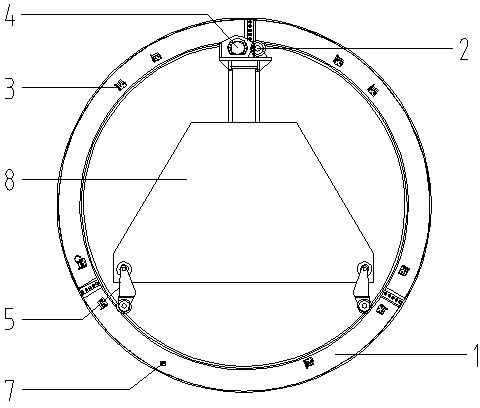
[0028] Such as figure 1 As shown, the steel arch assembling machine of this embodiment includes the main beam 8 of the roadheader, and three guide wheels are arranged on the main beam 8 of the roadheader, which are an upper guide wheel 2 and two lower guide wheels 5 respectively.

[0029] The upper guide wheel 2 is arranged directly above the main beam 8 of the roadheader, and a hydraulic motor 4 is arranged on the upper guide wheel 2, and the hydraulic motor 4 drives the ring beam 1 arranged outside the guide wheel to rotate through gear engagement. The guide wheel 2 is used to bear the weight of the ring beam and drive the ring beam to rotate.

[0030] The two lower guide wheels 5 are symmetrically arranged on the left and right sides of the main beam 8 of the roadheader with the longitudinal center line of the main beam 8 of the roadheader as the symmetrical axis, and are used to support the rotation of the ring beam 1. Orientation and radial positioning.

[0031] The who...

Embodiment 2

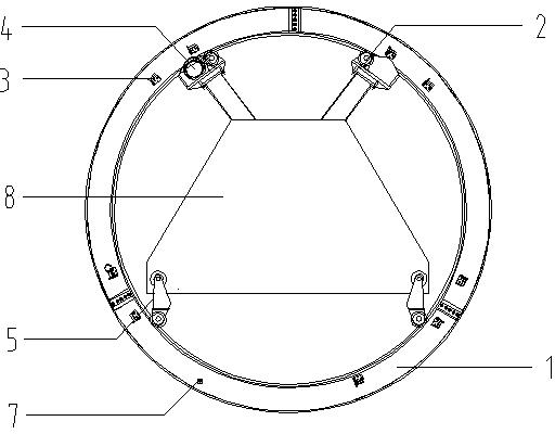
[0034] Such as figure 2 As shown, the structure of the steel arch assembly machine of this embodiment is basically the same as that of the steel arch assembly machine of the first embodiment. The longitudinal center line is symmetrically arranged on the left and right sides of the main beam 8 of the roadheader, and there is one hydraulic motor 4, which is arranged on one of the upper guide wheels 2. There are two bottom guide wheels 5, which are symmetrically arranged on the left and right sides of the roadheader main beam 8 with the longitudinal centerline of the roadheader main beam 8 as the symmetrical axis. The circular beam 1 is driven to rotate by a hydraulic motor 4 .

Embodiment 3

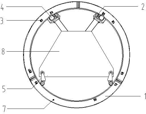
[0036] Such as image 3 As shown, the structure of the steel arch assembling machine of this embodiment is basically the same as that of the steel arch assembling machine of the second embodiment, the difference is that there are two hydraulic motors 4, which are located on one of the upper guide wheels 2 superior. There are two bottom guide wheels 5, which are symmetrically arranged on the left and right sides of the roadheader main beam 8 with the longitudinal centerline of the roadheader main beam 8 as the symmetrical axis. The circular beam 1 is driven to rotate by two hydraulic motors 4, which improves the driving force.


PUM


Abstract

The invention discloses a steel arch assembling machine which comprises a heading machine main beam (8). Guiding wheels are arranged on the heading machine main beam (8) and include the upper guiding wheel (2) and the lower guiding wheels (5), a hydraulic motor (4) is arranged on the upper guiding wheel (2), and a circular beam (1) with steel arch supports (3) and a positioning hinge pin (7) is connected with the guiding wheels in a sliding mode. The steel arch assembling machine of the structure is simple in structure and convenient to operate, arch assembling can be conveniently and rapidly carried out in the mode of rotating the circular beam, the shockproof effect is achieved through hydraulic oil cylinders installed on the lower guiding wheels, components of the steel arch assembling machine are prevented from being damaged by vibration, and influences of vibration of a heading machine on the arch assembling machine are reduced.

Description

technical field [0001] The invention relates to an assembling machine, especially a steel arch assembling machine. Background technique [0002] During the working process of the tunnel boring machine, when the surrounding rock of the tunnel is broken, it is necessary to assemble a large number of steel arch frames for surrounding rock support. The steel arch frame is generally spliced ​​by multiple sections of I-beam or H-beam. Due to the heavy weight of the steel arch, personnel cannot operate it manually, and machines are used to splice the end of the arch into a whole. [0003] The splicing speed of the current steel arch assembly machine often cannot meet the tunnel boring speed requirements of the tunnel boring machine, resulting in low construction speed. Contents of the invention [0004] The technical problem to be solved by the present invention is that the splicing speed of the steel arch assembling machine in the prior art is slow, and cannot meet the driving...

Claims


Application Information

Patent Timeline
Patent Type & Authority Applications(China)
IPC IPC(8): E21D15/58
Inventor 李建斌赵华高渐宝张玉峰陶磊
Owner CHINA RAILWAY ENGINEERING EQUIPMENT GROUP CO LTD
Why Eureka
Try Eureka