Combined suction layout method for controlling compressor stator corner separation

A combined suction and compressor technology, applied in pump control, mechanical equipment, machine/engine, etc., can solve the problem of limited effect of high-load blade angular separation control, and achieve the expansion of stable working range, improvement of efficiency, and improvement of complex The effect of flow structure

Active Publication Date: 2014-05-21
BEIHANG UNIV
View PDF2 Cites 12 Cited by
  • Summary
  • Abstract
  • Description
  • Claims
  • Application Information

AI Technical Summary

Problems solved by technology

At present, in the compressor stator, suction grooves are generally opened on the end wall or on the surface of the blade to control the corner separation, and the control effect on the corner separation of the high-load blade is limited.

Method used


Image

  • Combined suction layout method for controlling compressor stator corner separation
  • Combined suction layout method for controlling compressor stator corner separation
  • Combined suction layout method for controlling compressor stator corner separation

Examples


Embodiment Construction

[0014] Now, taking PVD cascade as an example, the present invention will be described in conjunction with the accompanying drawings.

[0015] According to an embodiment of the present invention, the combined suction slot layout scheme for controlling the separation of the corner area of ​​the stator blade cascade of the compressor includes:

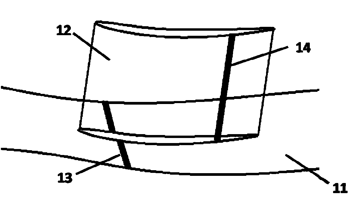
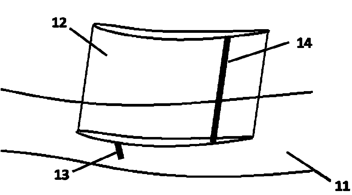
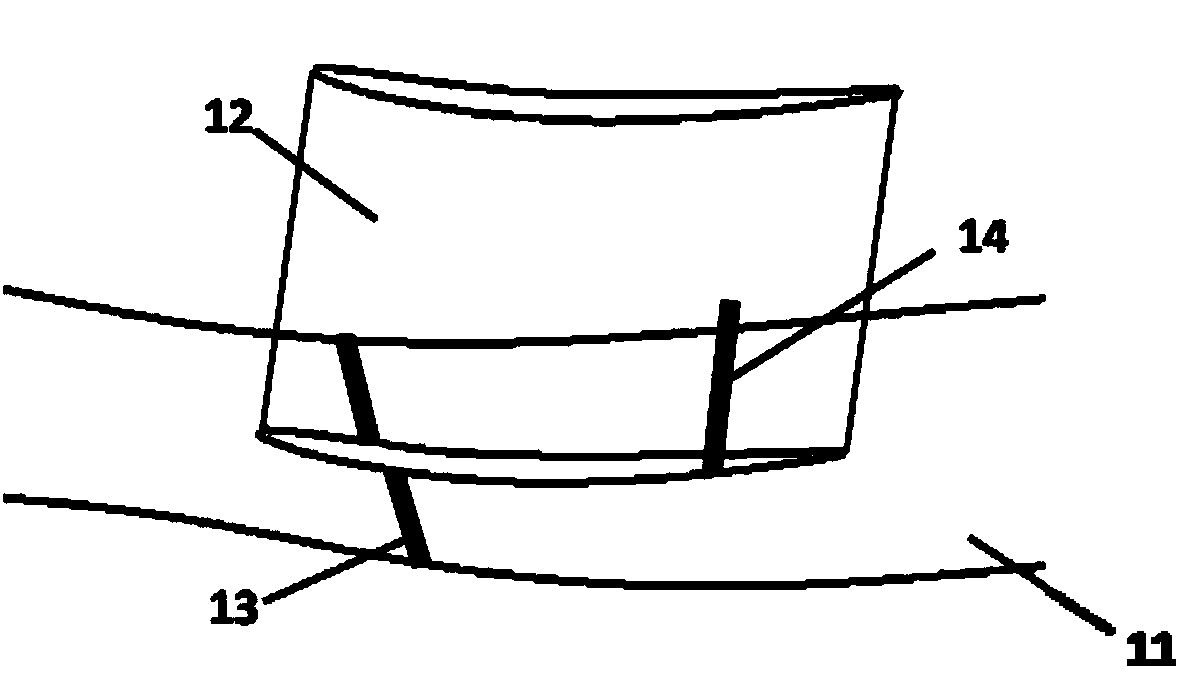
[0016] A) A suction slot is opened on the end wall of the stator cascade channel of the axial flow compressor. The length of the suction slot can be set according to the flow characteristics in the cascade. The maximum length of the suction slot is the length from the suction surface to the pressure surface of the adjacent blade. . Such as figure 1 Shown is an embodiment of the present invention, wherein the direction of the suction groove (13) on the end wall (11) is parallel to the forehead line, and the length of the suction groove is the maximum length; as figure 2 Shown is another embodiment of the present invention, wherein the l...


PUM


Abstract

The invention relates to a combined suction scheme for controlling compressor stator corner separation. The combined suction scheme is characterized in that a suction groove is formed in an end wall of an axial-flow compressor stator cascade channel circumferentially, a suction groove is formed in a blade suction surface in a blade height direction, a suction groove in the end wall is parallel to a forehead line, the control on different axial positions and different suction groove lengths can be realized, and the suction groove in the end wall and the suction groove in the blade suction surface can also be controlled through different combination forms of positions. Compared with a single suction scheme, the combined suction scheme can combine advantages of suction surface suction and end wall suction, so that the development of boundary layers on the suction surface and the end wall can be prevented more effectively, gathering and mixing of the boundary layers at corners can also be prevented, the corner separation can be inhibited obviously, the total pressure loss can be reduced, and the stability and the efficiency of a compressor can be improved.

Description

technical field [0001] The invention relates to a combined suction layout method for controlling the separation of stator corner areas of a compressor, and an axial flow compressor with the layout, belonging to the flow control technology in the technical field of turbomachinery. Background technique [0002] The design of modern turbomachinery is developing towards higher stage load, higher efficiency and higher stability. In the stator cascade, there is a boundary layer and the accumulation and mixing of low-energy fluids in the angular interval formed by the suction surface of the blade and the end wall of the hub, which will aggravate the three-dimensional separation in the cascade, and cause flow loss and flow blockage in the compressor. The main source of it, even cause stall and surge in severe cases. Therefore, how to control the corner separation in the compressor has become one of the key technologies to improve engine performance. [0003] At present, the main c...

Claims


Application Information

Patent Timeline
Patent Type & Authority Applications(China)
IPC IPC(8): F04D27/00F04D19/00
CPCF04D29/682
Inventor 柳阳威孙槿静梁斐杰陆利蓬
Owner BEIHANG UNIV
Why Eureka
Try Eureka