Cleaning device for cleaning a surface comprising a brush and a squeegee element

Pending Publication Date: 2014-07-03
KONINKLIJKE PHILIPS ELECTRONICS NV
View PDF25 Cites 38 Cited by
  • Summary
  • Abstract
  • Description
  • Claims
  • Application Information

AI Technical Summary

Benefits of technology

[0047]When brush elements come into contact with a dirt particle or liquid, or, in case an indentation of the brush with respect to the surface is set, the brush elements are bent. As soon as the brush elements with the dirt particles and liquid adhering thereto loose contact with the surface, the brush elements are straightened out, wherein especially the tip portions of the brush elements are moved with a relatively high acceleration. As a result the centrifugal acceleration at the top portions of the brush elements is increased. Hence, the liquid droplets and dirt particles adhering to the brush elements are launched from the brush elements, as it were, as the acceleration forces are higher than the adhesive forces, as this has been mentioned according to the embodiment above. The values of the acceleration forces are determined by various factors, including the deformation and the linear mass density as mentioned, but also by the speed at which the brush is driven.
[0048]A factor which may play an additional role in the cleaning function of the rotatable brush is a packing density of the brush elements. When the packing density is large enough, capillary effects may occur between the brush elements, which enhance fast removal of liquid from the surface to be cleaned. According to an embodiment of the present invention the packing density of the brush elements is at least 30 tufts of brush elements per cm2, wherein a number of brush elements per tuft is at least 500.
[0049]Arranging the brush elements in tufts forms additional capillary channels, thereby increasing the capillary forces of the brush for picking-up dirt particles and liquid droplets from the surface to be cleaned.
[0

Problems solved by technology

The sweeper, however, does not include a vacuum source and is therefore not able to pick-up water from the floor to be cleaned.
The performance on drying the floor is thus rather low.
However, the performance on drying the floor is rather low, since such an agitator is not able to lift liquid from the floor.
Moving the device in an opposite backward direction would leave the floor wet, since the cleaning water which is dispersed with the brush is not removed from the squeegees in this backward stroke.
Even though such double squeegee arrangements on both sides of the brush show good cleaning results, the nozzle of these devices become fairly bulky.
This again results in a non-satisfying, limited work capability.
Especially in household appliances where often narrow corners need to be cleaned, such bulky nozzles are, due to their limited liberty of action, disadvantages and uncomfortable to use.
Due

Method used


Image

  • Cleaning device for cleaning a surface comprising a brush and a squeegee element
  • Cleaning device for cleaning a surface comprising a brush and a squeegee element
  • Cleaning device for cleaning a surface comprising a brush and a squeegee element

Examples


first embodiment

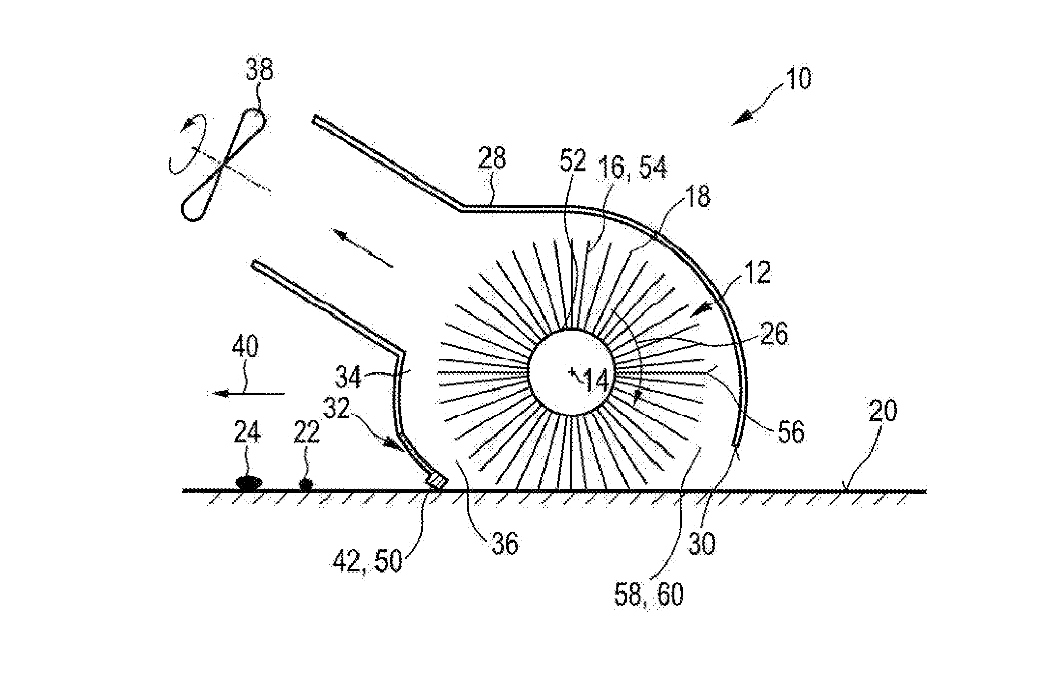
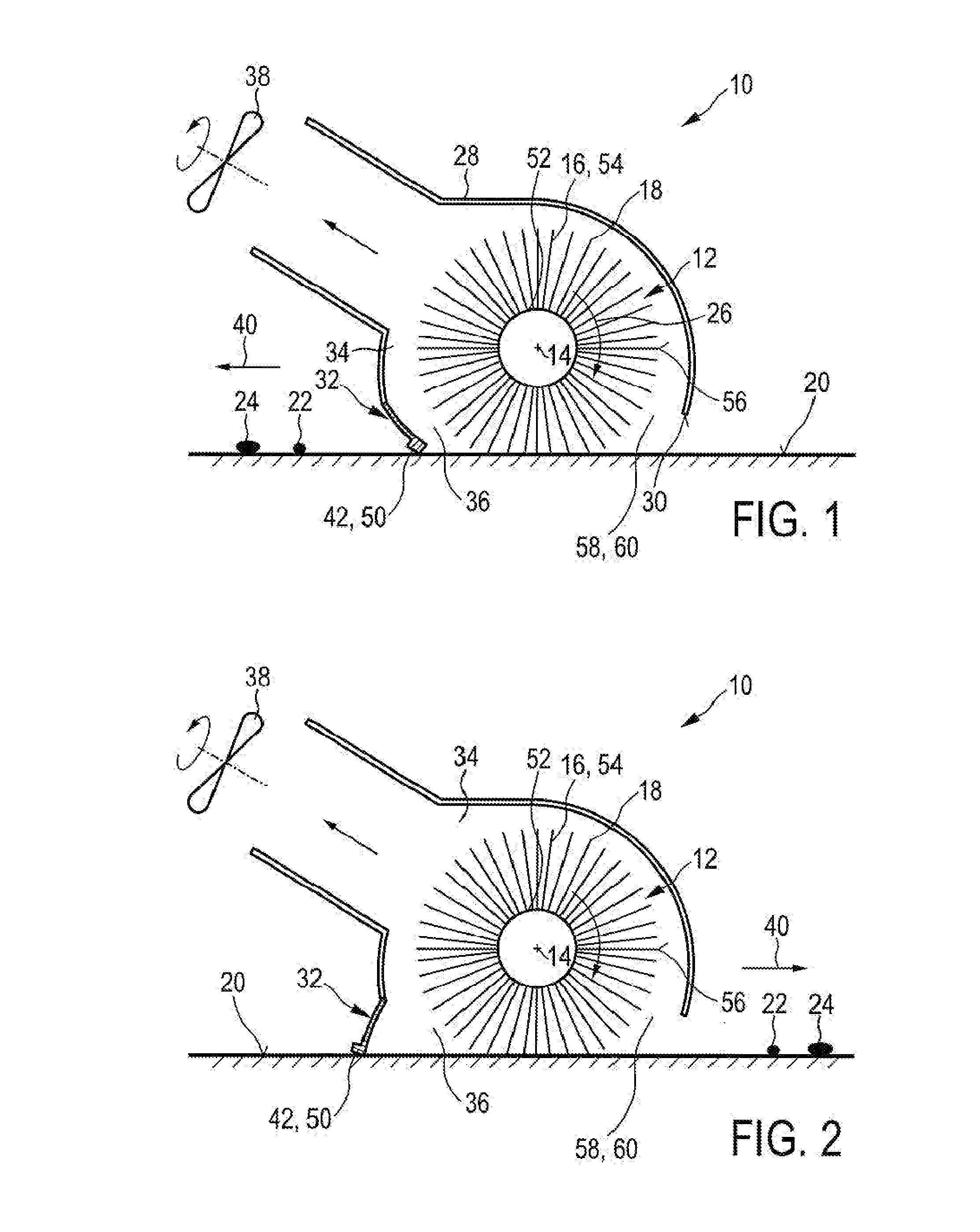
[0075]FIGS. 1 and 2 show a schematic cross-section of a nozzle arrangement 10 of a cleaning device 100 according to the present invention. In FIG. 1 the nozzle arrangement 10 is shown in a first working position, whereas in FIG. 2 the nozzle arrangement 10 is shown in a second working position. The nozzle arrangement 10 comprises a brush 12 that is rotatable about a brush axis 14. Said brush 12 is provided with flexible brush elements 16 which are preferably realized by thin microfiber hairs. The flexible brush elements 16 comprise tip portions 18 which are adapted to contact a surface to be cleaned 20 during the rotation of the brush 12 and to pick-up dirt particles 22 and liquid 24 from said surface 20 during a pick-up period when the brush elements 16 contact the surface 20.

[0076]A linear mass density of a plurality, preferably of a majority of the brush elements 16 is, at least at their tip portions 18, chosen to be lower than 150 g / 10 km. Further, the nozzle arrangement 10 comp...

second embodiment

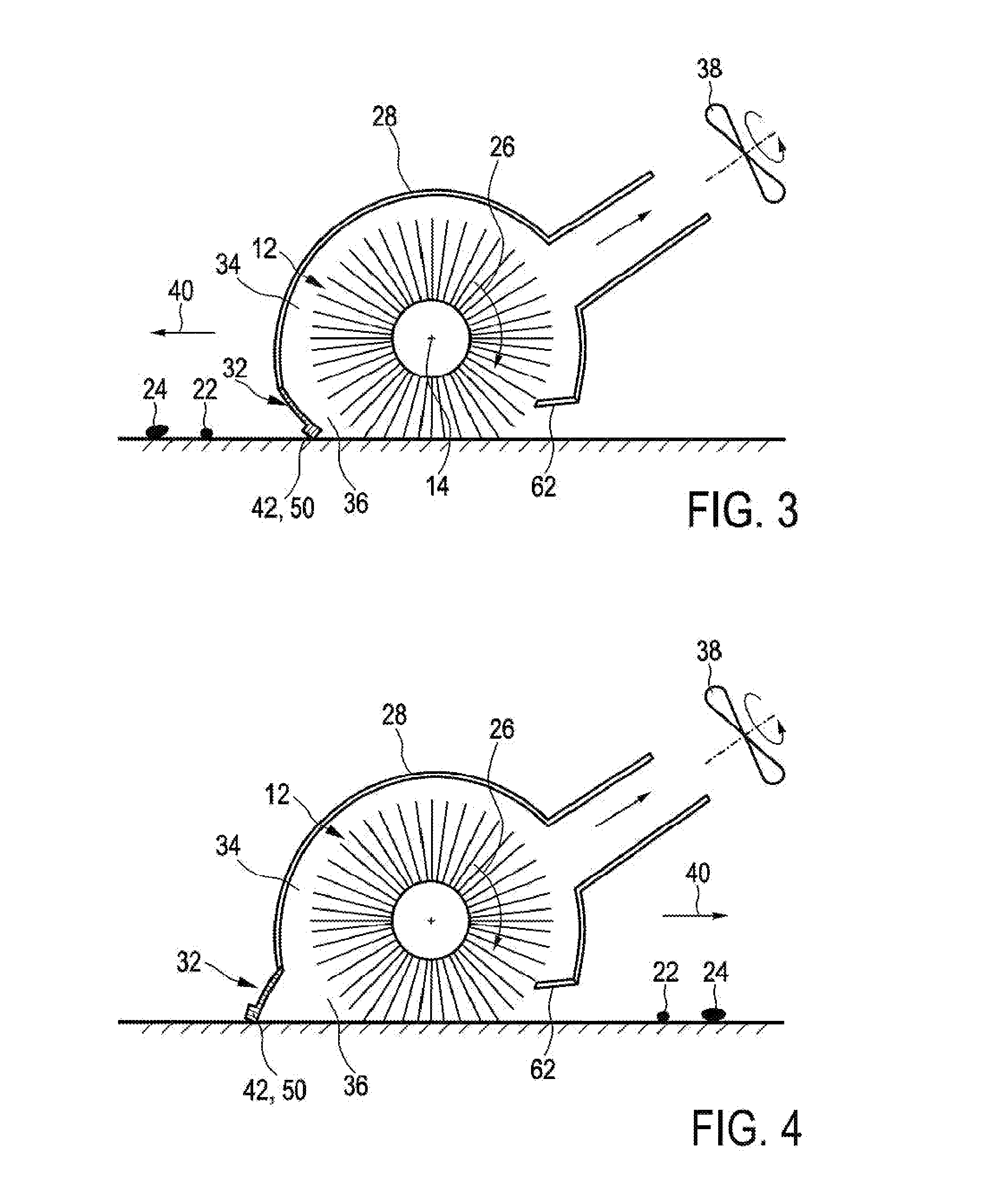
[0114]Furthermore, it is possible to use a deflector 62 for indenting the brush 12 at a position, seen in rotation direction 26, before the brush 12 contacts the surface 20, as this is exemplary shown in second embodiment which is shown in FIGS. 3 and 4. The deflector 62 has the function to press the brush elements 16 together by deflecting them. In this way air, which is present in the space between the brush elements 16, is pushed out of said space. When the brush elements 16 are, after leaving the deflector 62, moved apart from each other again, the space in between the brush elements 16 increases so that air will be sucked into the brush 12, wherein an under-pressure is created that sucks in dirt 22 and liquid particles 24. This again compensates for the air blow that is generated by the rotating brush 12. Examples of deflectors as mentioned are found in PCT / IB2009 / 054333 and PCT / IB2009 / 054334, both in the name of Applicant.

[0115]The airflow which needs to be compensated can be ...


PUM


Abstract

The present invention relates to a cleaning device for cleaning a surface (20), comprising: —a nozzle arrangement (10) that comprises i) a brush (12) rotatable about a brush axis (14), said brush (12) being provided with flexible brush elements (16) having tip portions (18) for contacting the surface to be cleaned (20) and picking up dirt particles (22) and liquid (24) from the surface (20) during a pick-up period when the brush elements (16) contact the surface (20) during the rotation of the brush (12), wherein a linear mass density of a plurality of the brush elements (16) is, at least at the tip portions (18), lower than 150 g per 10 km, and ii) a single squeegee element (32) for pushing or wiping dirt particles (22) and liquid (24) across or off the surface to be cleaned (20) during movement of the cleaning device (100), said squeegee element (32) being spaced apart from the brush (12) and extending substantially along a longitudinal direction (48) being substantially parallel to the brush axis (14), wherein a suction area (34) is defined within the nozzle arrangement (10) between the squeegee element (32) and the brush (12), —a drive means for driving the brush (12) in rotation, wherein the drive means are adapted to realize a centrifugal acceleration at the tip portions (18) which is, in particular during a dirt release period when the brush elements (16) are free from contact to the surface (20) during rotation of the brush (12), at least 3,000 m/s 2, and —a vacuum aggregate (38) for generating an under-pressure in the suction area (34) for ingesting dirt particles (22) and liquid (24).

Description

FIELD OF THE INVENTION[0001]The present invention relates to a cleaning device for cleaning a surface. Further, the present invention relates to a nozzle arrangement for such a cleaning device.BACKGROUND OF THE INVENTION[0002]Hard floor cleaning these days is done by first vacuuming the floor, followed by mopping it. Vacuuming removes the coarse dirt, while mopping removes the stains. From the state of the art many appliances, especially targeting the professional cleaning sector, are known that claim to vacuum and mop in one go. Appliances for the professional cleaning sector are usually specialized for big areas and perfectly flat floors. They rely on hard brushes and suction power to get water and dirt from the floor. Appliances for home use often use a combination of a hard brush and a squeegee nozzle. Like the appliances for the professional cleaning sector these products use the brush to remove stains from the floor and the squeegee in combination with an under-pressure to lif...

Claims


Application Information

Patent Timeline
IPC IPC(8): A47L9/04A47L11/40
CPCA47L9/0488A47L9/0477A47L11/4044A47L11/4041
Inventor VAN DER KOOI, JOHANNES TSEARDROUMEN, BRITT
Owner KONINKLIJKE PHILIPS ELECTRONICS NV
Why Eureka
Try Eureka