Pattern cooled turbine airfoil

a technology of airfoil and turbine engine, which is applied in the direction of machines/engines, sustainable transportation, climate sustainability, etc., can solve the problems of reducing the performance and efficiency of the turbine engine, reducing the efficiency of the film cooling, and the airfoil must be adequately cooled

Active Publication Date: 2007-07-31
GENERAL ELECTRIC CO
View PDF18 Cites 47 Cited by
  • Summary
  • Abstract
  • Description
  • Claims
  • Application Information

AI Technical Summary

Problems solved by technology

Blade cooling must be effected with minimum use of air bled from the compressor which bleed air correspondingly decreases performance and efficiency of the turbine engine.
However, the airfoils must be adequately cooled for obtaining a long useful life before experiencing undesirable thermal distress.
Each film cooling hole must have a suitable backflow margin to prevent ingestion of the combustion gases into the airfoil, but the backflow margin cannot be excessive or the discharge jet will separate from the external surface and reduce efficiency of the film cooling.
The typical diffusion film cooling hole typically requires electrical discharge machining (EDM) with a correspondingly shaped electrode that significantly increases the time and cost of manufacture.
The typical dilemma facing the designer is the selection of the fewest cooling holes with the simplest configuration for the different parts of the turbine airfoil for obtaining acceptable cooling thereof with minimal air bled from the compressor for maximizing airfoil life.
However, this long useful life of actual turbine blades in extended service has led to the discovery of localized thermal distress at the end of that long life.

Method used


Image

  • Pattern cooled turbine airfoil
  • Pattern cooled turbine airfoil
  • Pattern cooled turbine airfoil

Examples


Embodiment Construction

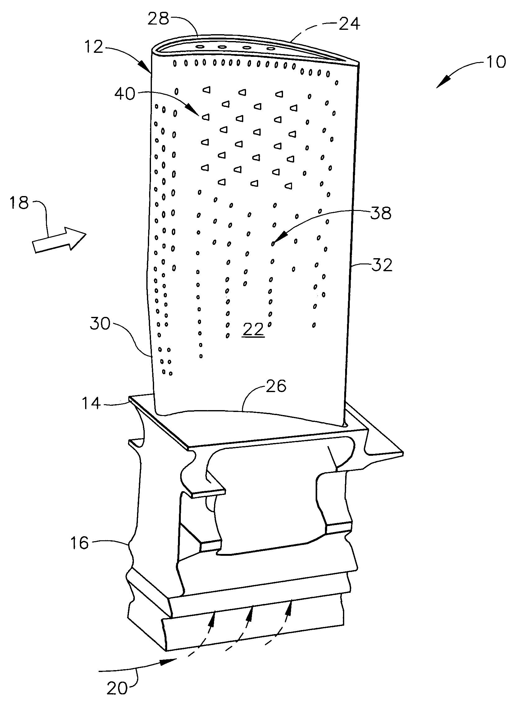
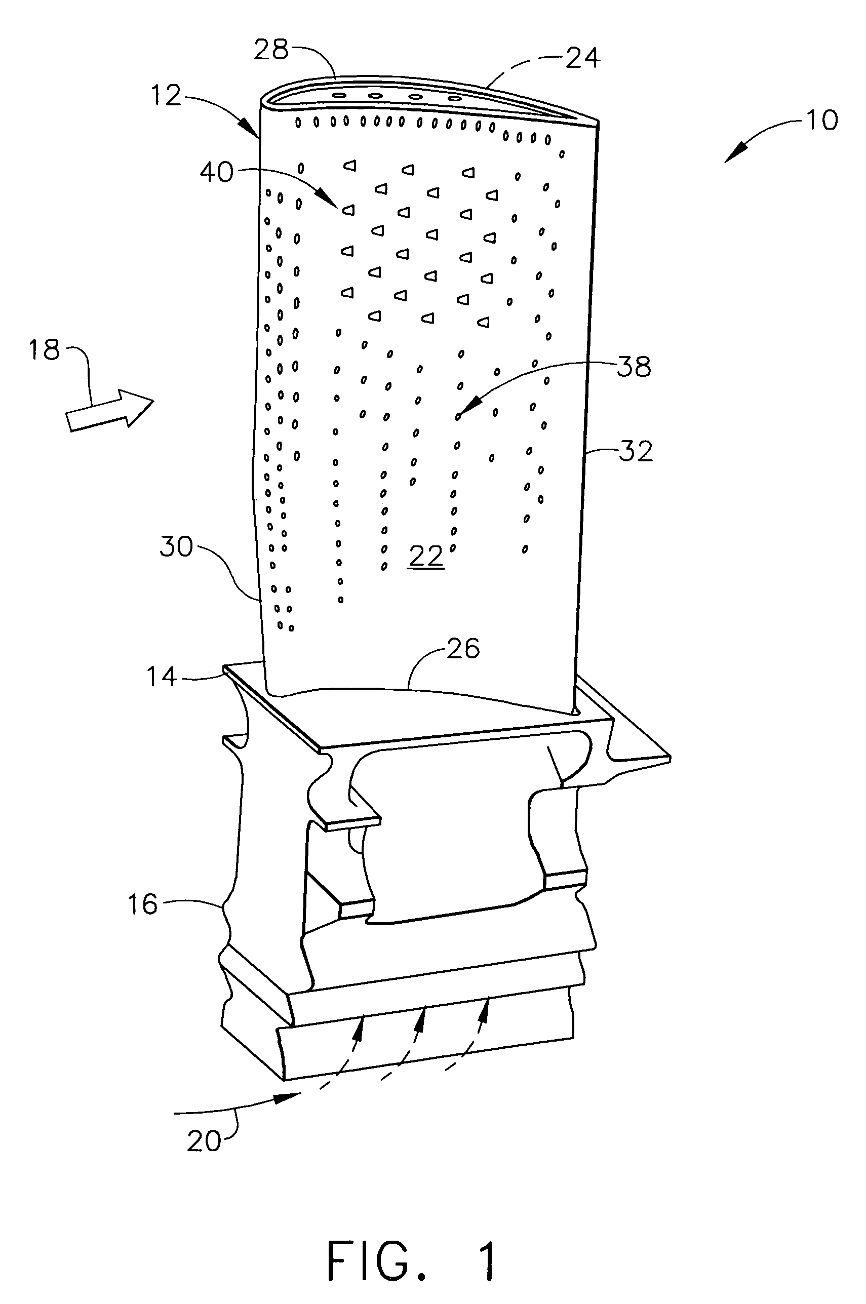
[0035]Illustrated in FIG. 1 is an exemplary, first stage turbine rotor blade 10 for use in a gas turbine engine. The blade includes an airfoil 12, platform 14, and supporting dovetail 16 formed in a unitary configuration by casting. The platform defines a radially inner boundary for hot combustion gases 18 generated in an upstream combustor (not shown) which flow axially downstream over the airfoil 12 during operation.

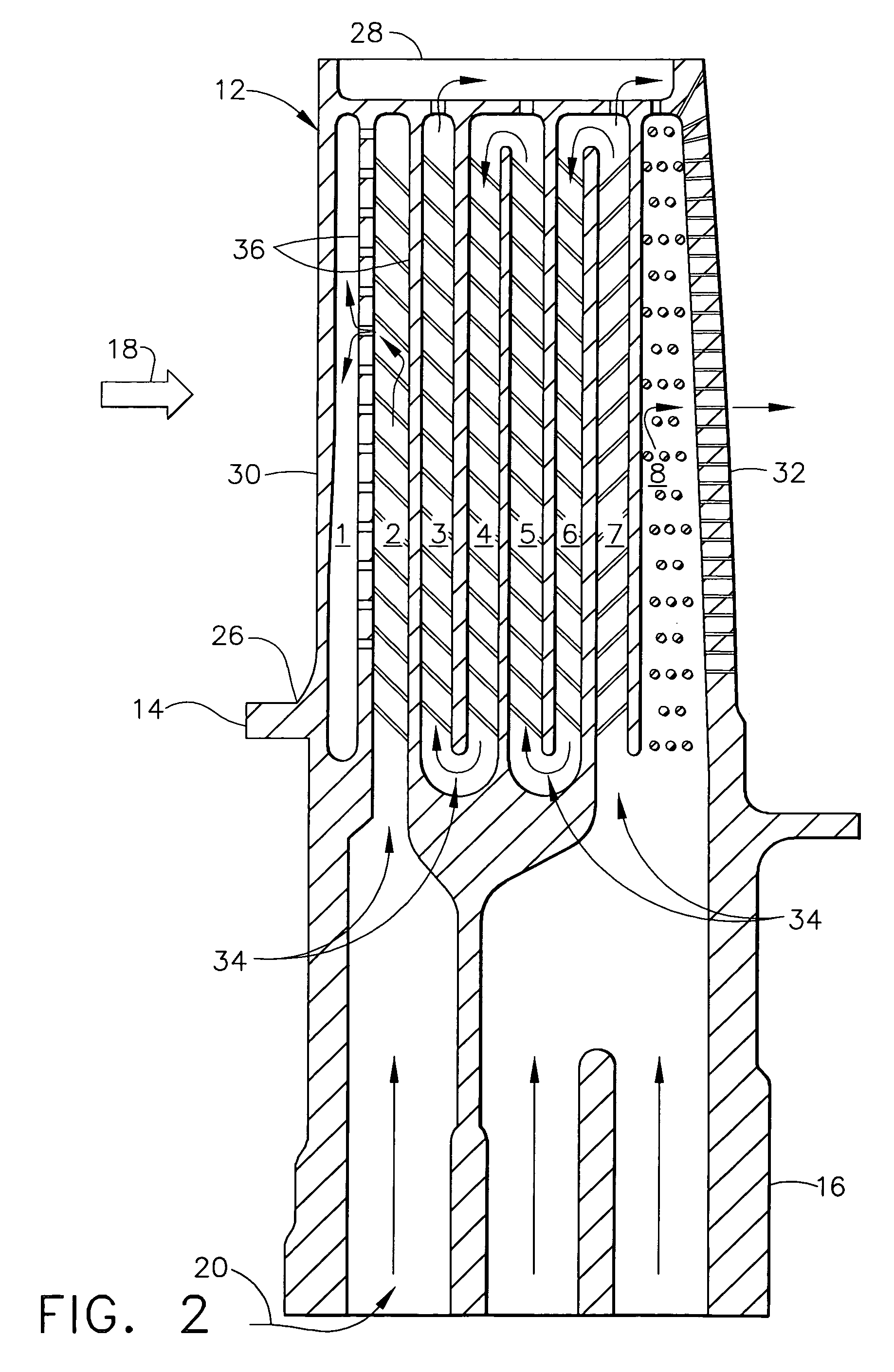
[0036]The airfoil 12 is hollow for receiving a cooling air coolant 20 through corresponding inlets in the base of the dovetail 16 for cooling the blade during operation. The dovetail 16 is configured with supporting lobes or tangs that mate with a corresponding dovetail slot in the perimeter of a supporting rotor disk (not shown) from which the blade extends radially outwardly in the engine.

[0037]The disk includes a full row or complement of the blades 10 for extracting energy from the combustion gases for rotating the disk and in turn powering the compressor (not show...


PUM


Abstract

A hollow turbine airfoil includes pressure and suction sidewalls extending in span between a root and tip and extending in chord between opposite leading and trailing edges. The pressure sidewall includes a first pattern of first holes distributed in span and chord over a majority thereof, and a second pattern of different second holes also distributed in span and chord over a minority of the pressure sidewall between the tip and the midspan of the airfoil.

Description

BACKGROUND OF THE INVENTION[0001]The present invention relates generally to gas turbine engines, and, more specifically, to turbine rotor blades therein.[0002]In a gas turbine engine, air is pressurized in a compressor and mixed with fuel in a combustor for generating hot combustion gases. A high pressure turbine (HPT) follows the combustor and extracts energy from the combustion gases for powering the compressor. A low pressure turbine (LPT) follows the HPT and extracts additional energy from the combustion gases for powering an upstream fan in an aircraft turbofan engine application, or powers an external drive shaft for marine and industrial applications.[0003]The turbines are arranged in stages including a stationary turbine nozzle having a row of vanes which direct the combustion gases into a corresponding row of turbine rotor blades. Each vane has an airfoil configuration extending radially in span between inner and outer bands which bound the combustion gases.[0004]Each turbi...

Claims


Application Information

Patent Timeline
Patent Type & Authority Patents(United States)
IPC IPC(8): F01D5/18
CPCF01D5/186Y02T50/673Y02T50/676F01D5/20Y02T50/60
Inventor PALMER, NICHOLAS CHARLESKIRKENG, KEVIN LEELEE, CHING-PANG
Owner GENERAL ELECTRIC CO
Why Eureka
Try Eureka