Heat exchange ventilation device
A ventilation device and heat exchanger technology, which is applied in the direction of household heating, household heating, heating methods, etc., can solve the problems of reduced construction, difficult installation, and increased product area, so as to suppress height dimensions and ensure The effect of air volume
- Summary
- Abstract
- Description
- Claims
- Application Information
AI Technical Summary
Problems solved by technology
Method used
Image
Examples
no. 1 approach
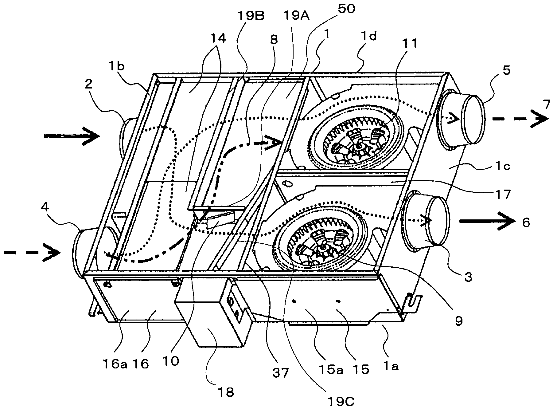
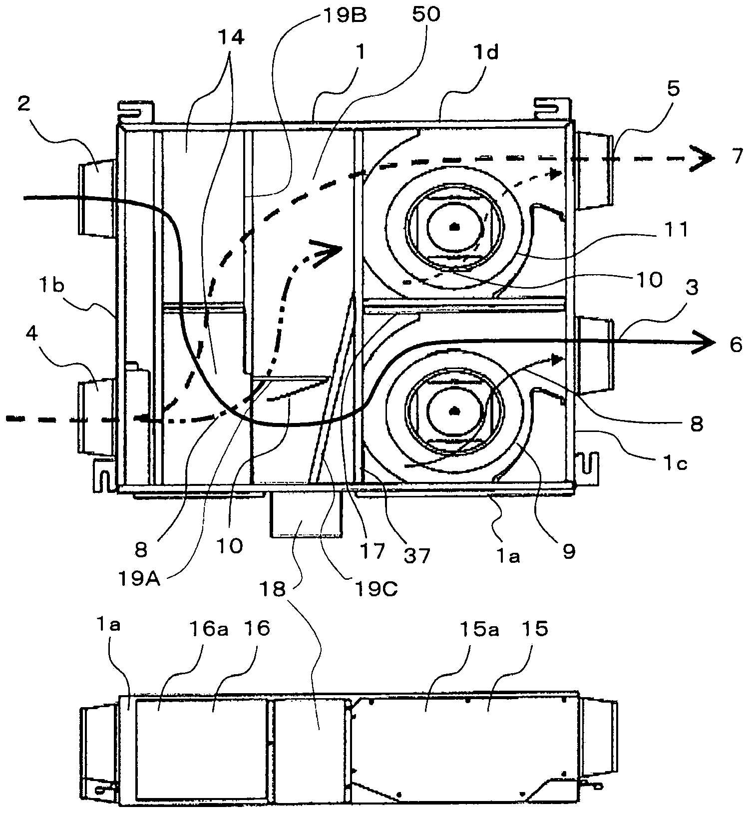
[0040] figure 1 It is a perspective view schematically showing the structure of the heat exchange ventilation device of the first embodiment of the present invention, figure 2 It is a plan view which schematically shows the structure of the heat exchange ventilator which concerns on 1st Embodiment of this invention. figure 2 (A) is a plan view of the heat exchange and ventilation device according to the first embodiment of the present invention viewed from the upper surface, figure 2 (B) is the plan view which looked at the heat exchange ventilator which concerns on 1st Embodiment of this invention from a side.
[0041] in addition, figure 1 with figure 2 It is the figure of the state which removed the top plate attached to the upper part of the heat exchange ventilator.
[0042] A heat exchange ventilator is a device that takes in air from an air-conditioning target space (such as a house, building, warehouse, etc.) and discharges it outside the air-conditioning tar...
no. 2 approach
[0109] Figure 8 It is a figure showing the detachment mode and direction of the air supply blower unit 9 of the heat exchange ventilator of the second embodiment of the present invention, Figure 9 It is a figure which shows the detachment form and direction of the exhaust blower unit 11 of the heat exchange ventilator of the 2nd Embodiment of this invention, Figure 10 It is a perspective view which shows the periphery of the indoor side blowing opening part 3a seen from the blower side opening part 15a of the heat exchange ventilator which concerns on 2nd Embodiment of this invention. In the second embodiment, the difference from the first embodiment will be mainly described, and the description of the common parts will be omitted.
[0110] An air supply blower maintenance panel 15 is attached to the indoor side surface 1a for closing the blower side opening 15a which is a maintenance opening for blower maintenance.
[0111] In addition, the indoor side blowing opening 3a...
no. 3 approach
[0129] In the third embodiment, the difference from the first and second embodiments will be mainly described, and the description of the common parts will be omitted. refer to the above Figure 1 to Figure 4 , the heat exchange ventilator of the third embodiment will be described.
[0130] The heat exchange and ventilation device has: a housing 1, a heat exchanger 14, a supply air blower unit 9, an exhaust blower unit 11, and is used to switch whether the outdoor air sucked into the housing 1 is discharged after passing through the heat exchanger 14. The opening and closing valve 10, the driving motor 21 that makes the opening and closing valve 10 open and close (refer to Figure 13 ), a control device for controlling the drive motor 21, and a circuit box 18 for accommodating the drive motor 21 and the like.
[0131] (housing 1)
[0132] The casing 1 is a substantially rectangular parallelepiped box, constituting the outer contour of the heat exchange ventilator, and has a...
PUM
 Abstract
Description
Claims
Application Information
 - R&D
- Intellectual Property
- Life Sciences
- Materials
- Tech Scout
- Unparalleled Data Quality
- Higher Quality Content
- 60% Fewer Hallucinations
Browse by: Latest US Patents, China's latest patents, Technical Efficacy Thesaurus, Application Domain, Technology Topic, Popular Technical Reports.
© 2025 PatSnap. All rights reserved.Legal|Privacy policy|Modern Slavery Act Transparency Statement|Sitemap|About US| Contact US: help@patsnap.com


