
Optical touch system and method for determining positions of objects using the same

An optical touch and object technology, applied in the input/output process of data processing, instruments, electrical digital data processing, etc., can solve the problems of stripping, skewing, and increasing costs, avoiding falling off or skewing, and easy assembly. , the effect of reducing costs

Active Publication Date: 2014-05-21
WISTRON CORP
View PDF4 Cites 6 Cited by
  • Summary
  • Abstract
  • Description
  • Claims
  • Application Information

AI Technical Summary

Problems solved by technology

[0003] However, the aforementioned two optical touch systems must use side bars, which not only increases the cost, but also increases the complexity of assembly
Furthermore, the edge fixing technology is mostly glued to the touch surface at present, so it is easy to cause the problem of edge falling or skewing, which affects the judgment of the position of the object

Method used


Image

  • Optical touch system and method for determining positions of objects using the same
  • Optical touch system and method for determining positions of objects using the same
  • Optical touch system and method for determining positions of objects using the same

Examples


Embodiment Construction

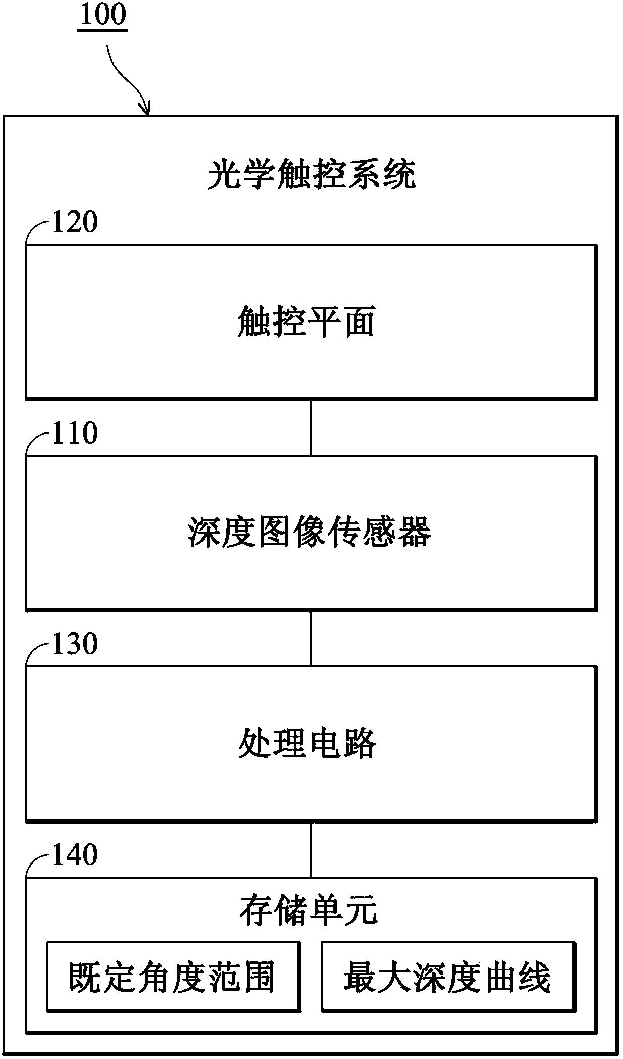
[0032] figure 1 A schematic diagram of an optical touch system 100 according to an embodiment of the present invention is shown. The optical touch system 100 according to the embodiment of the present invention can be applied to an electronic device, such as a personal digital assistant, a personal digital assistant mobile phone, a smart phone, a mobile phone, a mobile Internet device, or a mini notebook computer, a tablet computer, a car computer , digital camera, multimedia player, gaming device, or any type of mobile computing device, however, it should be understood that the present invention is not limited thereto. For example, in one embodiment, the optical touch system 100 can be used as a touch input device of a tablet computer for various touch inputs and operations, but is not limited thereto. The optical touch system 100 at least includes a depth image sensor 110 , a touch plane 120 , a processing circuit 130 and a storage unit 140 . The depth image sensor 110 (fo...


PUM


Abstract

The invention provides an optical touch system and a method for determining the positions of objects using the same. The optical touch system at least includes a depth image sensor and a touch plane, the depth image sensor having a sensing area covering the touch plane. First, when an object is detected by the depth image sensor, image information is obtained by using the depth image sensor, wherein the image information includes angle information and depth information related to the depth image sensor for the object. Thereafter, it is determined whether a position of the object is located at the inside or the outside of the touch plane according to the angle information and the depth information. The optical touch system and the method for determining positions of objects of the present invention can utilize depth information provided by the depth image sensor and matched with simple side limits, thereby without side bar technique can be achieved, so, its touch plane has no need to be installed with additional side bars, thus reducing cost and making product assembling more easier. Moreover, side bars are not needed for the touch plane, and thus free of side bar shed or distorted problems.

Description

technical field [0001] The present invention relates to an optical touch system and a method for judging the position of an object thereof, in particular to an optical touch system applicable to a touch plane without side bars and a method for judging the position of an object thereof. Background technique [0002] In recent years, since more and more devices can use touch input operation instructions, in some electronic devices, such as smart phones (smart phones), personal digital assistants (PDAs), tablet computers (Tablet PCs) or ultra-portable computers ( UMPC, Ultra Mobile PC, etc., are all equipped with a touch screen that can be directly touched, and can be used as a main input device in a touch operation mode. The touch display device incorporates an optical touch system with a touch surface including at least one-dimensional sensors for detecting contact and movement of objects such as fingers or stylus on the surface. Currently, there are two common types of opti...

Claims


Application Information

Patent Timeline
Patent Type & Authority Applications(China)
IPC IPC(8): G06F3/042
CPCG06F3/0425
Inventor 谢升宪黄博亮魏守德林瑞建
Owner WISTRON CORP
Features
  • Generate Ideas
  • Intellectual Property
  • Life Sciences
  • Materials
  • Tech Scout
  • Unparalleled Data Quality
  • Higher Quality Content
  • 60% Fewer Hallucinations
Learn More