RFID antenna system

An antenna system, 1. RFID technology, applied in the field of RFID antenna systems, can solve the problems of unsatisfactory transmission distance and high cost of antenna systems

Inactive Publication Date: 2014-05-21
姜韫英
View PDF0 Cites 2 Cited by
  • Summary
  • Abstract
  • Description
  • Claims
  • Application Information

AI Technical Summary

Problems solved by technology

The cost of the existing antenna system is relative

Method used


Image

  • RFID antenna system

Examples


Embodiment Construction

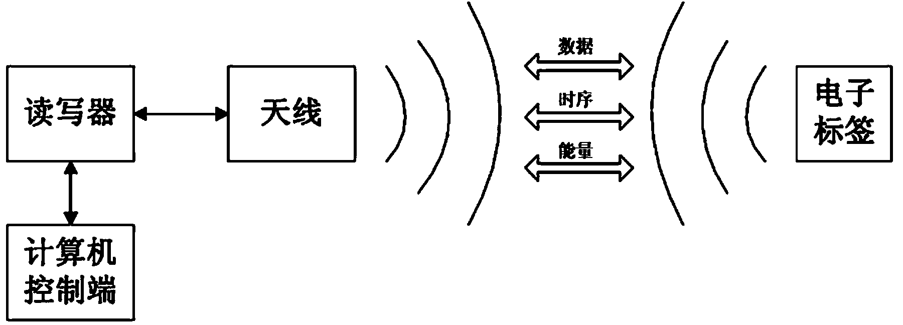
[0011] As shown in the figure, the present invention includes a control terminal, a reader-writer, an antenna, and an electronic tag, and the control terminal, the reader-writer, and the antenna are connected in sequence.

[0012] The reader includes a DSP microprocessor, a radio frequency analog front end, and a matching circuit, and the DSP microprocessor, the radio frequency analog front end, the matching circuit, and an antenna are connected in sequence.

[0013] The control terminal is a computer.

[0014] The reader emits energy through the antenna to form an electromagnetic field to identify the electronic tag. The range of the electromagnetic field formed by the antenna is the readable and writable area of ​​the radio frequency identification system. The signal Tx carrier frequency from the reader to the card is 13.56MHz, and the signal Rx carrier frequency from the card to the reader is 14.41MHz. A 13.56MHz RFID antenna is designed according to the requiremen...


PUM


Abstract

An RFID antenna system belongs to the technical filed of an antenna system. The invention especially relates to an RFID antenna system and provides an RFID antenna system with a low cost and a long transmission distance. The RFID antenna system comprises a control end, a reader-writer, an antenna and an electronic label. The main points of the structure are that the control end, the reader-writer and the antenna are successively connected.

Description

technical field [0001] The invention belongs to the technical field of antenna systems, and in particular relates to an RFID antenna system. Background technique [0002] As a non-contact automatic identification technology, radio frequency identification (RFID) technology uses radio frequency signals to achieve non-contact information transmission through spatial coupling (alternating magnetic field or electromagnetic field) and achieve the purpose of identification through the transmitted information. Compared with other identification technologies, radio frequency identification technology has many advantages, such as non-contact, convenient and fast, large amount of stored information, fast identification, ability to identify multiple tags at the same time, and ability to penetrate non-metallic and other characteristics. Especially with the rapid development of electronic technology and the continuous improvement of manufacturing technology, the development of radio freq...

Claims


Application Information

Patent Timeline
IPC IPC(8): G06K17/00
Inventor 姜韫英蒋国敬
Owner 姜韫英
Why Eureka
Try Eureka