
Image rendering method and system

An image rendering and image frame technology, applied in the field of image rendering methods and systems, can solve the problems of time-consuming, difficulty in clearing template registers, etc.

Active Publication Date: 2014-05-21
RIGHTWARE
View PDF6 Cites 34 Cited by
  • Summary
  • Abstract
  • Description
  • Claims
  • Application Information

AI Technical Summary

Problems solved by technology

While clearing the template registers is not particularly difficult, just by writing a predetermined value to each template register, writing that predetermined value to each template register is a rather slow process if there are thousands of template registers
For example, when rendering shadows, doing this multiple times will be extremely time-consuming

Method used


Image

  • Image rendering method and system
  • Image rendering method and system
  • Image rendering method and system

Examples


Embodiment Construction

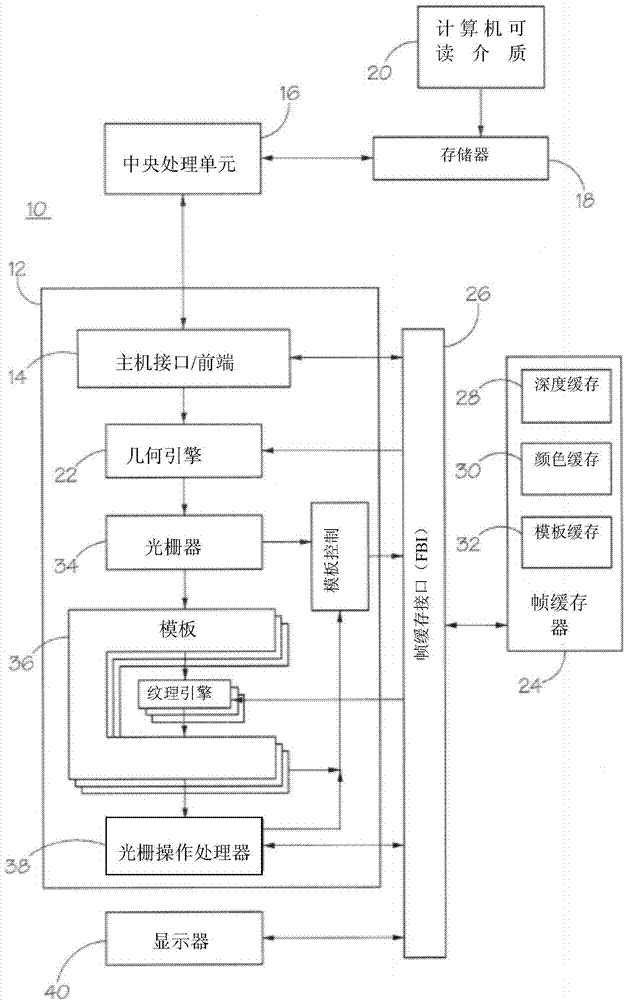
[0086] First refer to figure 1 , which shows a simplified block diagram of a computer system 10 embodying the principles of the invention. Computer system 10 includes a graphics processing unit 12 that integrates circuitry with a host interface / front end 14 . Host interface / front end 14 receives raw graphics data and program instructions from central processing unit 16 , which runs application programs stored in memory 18 . Application programs importable from computer readable medium 20 enable computer system 10 to implement the principles of the present invention.

[0087] Host interface / front end 14 buffers input information and provides raw graphics information to geometry engine 22 . Geometry engine 22 may access frame buffer 24 via frame buffer interface 26 . Geometry engine 22 generates, scales, rotates, and projects the 3D vertices of primitives stored in "model" coordinates in frame buffer 24 into 2D frame buffer coordinates.

[0088] The frame buffer 24 includes:...


PUM


Abstract

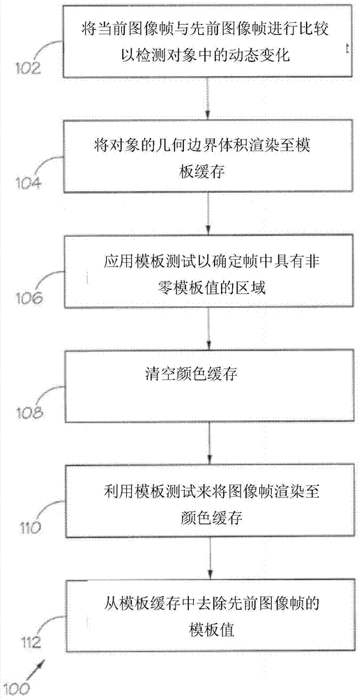
An image rendering method is provided, comprising comparing a current image frame with a previous image frame to detect a dynamic change in an object in the image frames, with each image frame being defined by a scene graph and each object having an associated geometric bounding volume. If a dynamic change in an object is detected, the method comprises rendering the object's geometric bounding volume to a stencil buffer for each dynamically changed object, using a stencil value assigned to the current image frame. A stencil is then applied to determine areas in the frames having non-zero stencil values. The method further comprises clearing a color buffer with respect to the areas in the previous image frame that have been redrawn and with respect to areas in the current frame that need to be overdrawn, rendering the image frame to the color buffer using a stencil test, so that only the areas with non-zero stencil values are redrawn, and then removing the stencil values from a previous image frame from the stencil buffer.

Description

technical field [0001] The present invention relates to an image rendering method and system, in particular, the present invention relates to a method and system for processing only those segments of an image frame that have changed compared to a previous image frame. Background technique [0002] The processing and rendering of graphics images is an important feature of modern computer systems. In image processing, mathematical processes are performed on a display to render or draw primitives such as triangles or rectangles to produce the desired visual image. Real-time graphics processing is based on the high-speed processing of primitives to produce visually pleasing moving images. [0003] To improve image quality, shadow generation techniques such as stenciled shadow volumes are introduced to add realistic shadows to rendered images. The stencil shadow volume technique relies on the use of a stencil buffer, which is described in more detail below. [0004] Typically,...

Claims


Application Information

Patent Timeline
Patent Type & Authority Applications(China)
IPC IPC(8): G06T15/00
Inventor 托马斯·沃洛蒂宁丹尼斯·库金金
Owner RIGHTWARE
Learn More