
Method for drawing volume rendering cutting surface

A volume rendering and surface rendering technology, applied in the field of 3D image visualization, can solve complex and computationally heavy problems, achieve the effects of good integration, reduce logical operations, reduce repeated calculations and spatial logic judgments

Active Publication Date: 2011-05-25
LANWON TECH
View PDF7 Cites 21 Cited by
  • Summary
  • Abstract
  • Description
  • Claims
  • Application Information

AI Technical Summary

Problems solved by technology

[0006] In the prior art, the clipping plane is generally regarded as a mathematical plane, and then the intersection point is obtained through analysis based on the intersection of the straight line and the plane. This method is more convenient when the perspective volume is drawn with a regular intersection, but once the perspective is rotated, each surface needs to be Mathematical analysis, at the same time, the result of the intersection point needs to be judged before and after the enclosing volume, the calculation amount is large and complex, and the processing of the clipping plane of the perspective requires more judgments to obtain its spatial logic relationship

Method used


Image

  • Method for drawing volume rendering cutting surface
  • Method for drawing volume rendering cutting surface
  • Method for drawing volume rendering cutting surface

Examples


Embodiment Construction

[0052] Below according to accompanying drawing and embodiment the present invention will be described in further detail:

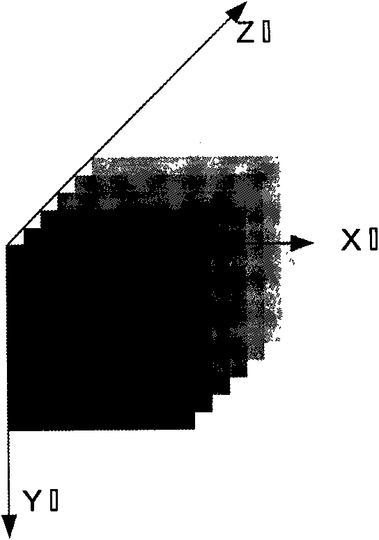
[0053] According to the tag definition of the DICOM standard, the present invention first unifies the sequence images into the same coordinate system, and then performs processing in the unified coordinate system.

[0054] Technical scheme of the present invention is as follows:

[0055] 1. Establish a unified coordinate system according to the TAG mark in the DICOM standard.

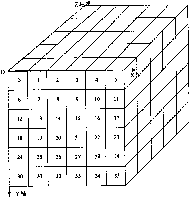
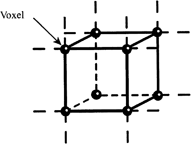
[0056] 2. Establish the data body structure.

[0057] 3. Calculate the clipping parameters according to the projection direction of the viewing angle.

[0058] 4. The ray tracing algorithm processes the clipping surface and completes the drawing.

[0059] The sequence images are digital images in the medical field and images of the DICOM standard for communication. The content of a DICOM image file consists of two parts: the file header (Header) that saves parameter information ...


PUM


Abstract

The invention provides a method for drawing a volume rendering cutting surface. Aiming at two conventional cutting modes, an in-and-out intersection point quick jumping cutting method is adopted, and the cutting surface is subjected to special light treatment so as to draw the cutting surface. The method has a high speed and a drawing result is favorable for observation and medical diagnosis. A one-time surrounding body method and deep judgment are adopted, the one-time surrounding body is needed to be solved for data volume, the method is well integrated with a ray tracing algorithm, multiple times of repetitive computation and the judgment of spatial logic are reduced, judgment in the ray tracking is not needed for a view angle cutting surface, logic operation is reduced, and the cutting surface is subjected to special illumination computation, so that the drawn cutting surface has a smooth effect and is convenient to observe.

Description

technical field [0001] The invention provides a three-dimensional image visualization technology, in particular to a volume rendering clipping surface rendering method. Background technique [0002] In medical imaging engineering, medical imaging equipment such as CT and MR all produce two-dimensional tomographic images of a certain part of the human body, and a series of parallel two-dimensional tomographic images are used to record the three-dimensional information of the human body. In medical diagnosis, medical personnel observe Multiple sets of two-dimensional tomographic images are used to reconstruct the three-dimensional data in the brain to determine the spatial structure of the lesion. This makes it difficult to accurately determine the spatial location, size, geometric shape and relationship with surrounding biological tissues of the lesion. Therefore, generating 3D images from a series of 2D tomographic images is increasingly needed and urgent in medical diagnos...

Claims


Application Information

Patent Timeline
Patent Type & Authority Applications(China)
IPC IPC(8): G06T17/00G06T15/50
Inventor 吕广志丁亮
Owner LANWON TECH
Learn More