
How to make a transparent antenna

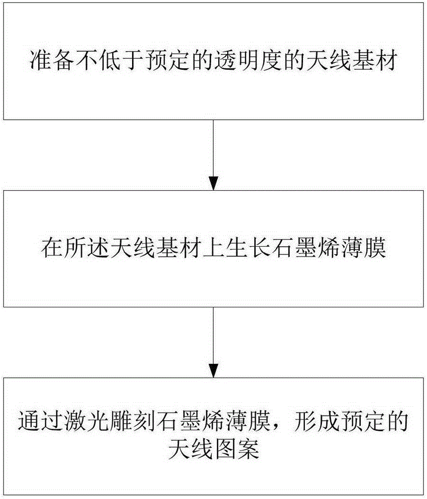
A manufacturing method and antenna technology, applied in antenna support/mounting device, gaseous chemical plating, metal material coating process, etc., can solve problems such as unfulfilled requirements and limitations

Active Publication Date: 2016-03-09
KUNSHAN RUIXIANG XUNTONG COMM TECHCO
View PDF2 Cites 0 Cited by
  • Summary
  • Abstract
  • Description
  • Claims
  • Application Information

AI Technical Summary

Problems solved by technology

For example, the design of mobile phone antennas is often limited by the internal space, and cannot achieve higher requirements
In addition, due to the personalized needs of customers, mobile phone manufacturers often design unique mobile phones to meet customers. Guaranteed adequate performance

Method used


Image

  • How to make a transparent antenna
  • How to make a transparent antenna
  • How to make a transparent antenna

Examples


Embodiment 1

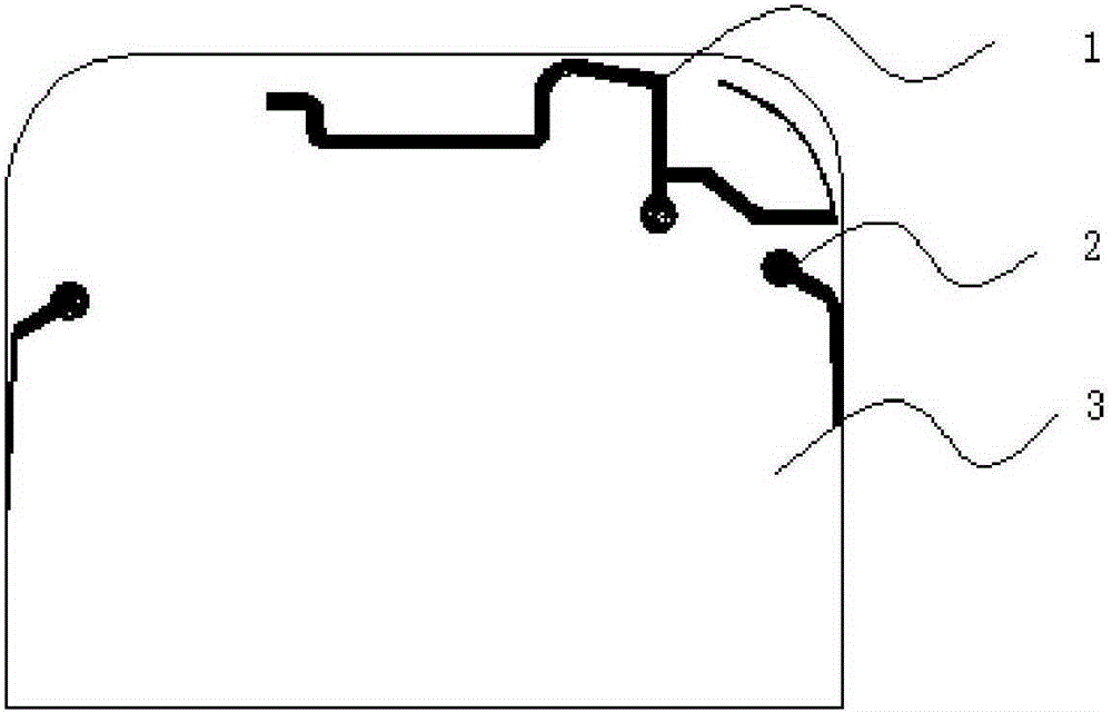
[0057] refer to figure 1 , Figure 1a and Figure 1b .

[0058] 1. Select glass as the antenna substrate

[0059] Glass surface treatment, polishing process conditions:

[0060] The concentration of polishing liquid is 1.1, the spindle speed is 25R / M, the pressure is 60KG, and the time is 40min.

[0061] 2. Cleaning

[0062] Ultrasonic process cleaning, ultrasonic power 60W, ultrasonic frequency 40KHz, heating power 100W, temperature 55 ℃, time 10min. The drying temperature is 55°C, and the drying time is 8 minutes.

[0063] 3. Use a jig to expose the antenna pattern. The size of the antenna pattern is controlled to 0.05~1mm, and all other parts are covered. There is a cushioning material on the jig contacting the antenna carrier to avoid scratching the antenna substrate.

[0064] 4. Growth of graphene nanofilm on glass

[0065] First turn on the vacuum pump, vacuum, when the vacuum reaches 10 -6 , the substrate glass is heated, the temperature is raised to 450°C, clo...

Embodiment 2

[0070] refer to figure 2 , Figure 2a and Figure 2b .

[0071] 1. Prepare the antenna substrate film, preferably PET film, preferably with a thickness of 0.1-0.15 mm, more preferably 0.11 mm. Thin films such as PMMA and PC can also be used.

[0072] 2. Coating graphene nano-film on PET film sheet

[0073] First turn on the vacuum pump, vacuum, when the vacuum reaches 10 -6 , heat the PET sheet, raise the temperature to 215°C, and fill it with inert gas and carrier gas, and control the flow rate; when the temperature in the center of the furnace body reaches 1000°C, feed the carbon source, control the flow rate, start deposition, and keep it for 25 minutes, with the help of carrier gas Cool to room temperature.

[0074] 3. Make PET graphene transparent antenna sheet

[0075] First, directly import the antenna pattern on the laser machine software, or draw it directly, and use the laser to engrave the antenna pattern to make a PET graphene antenna sheet. One PET graphe...


PUM

PropertyMeasurementUnit
thicknessaaaaaaaaaa
thicknessaaaaaaaaaa

Abstract

Disclosed is a manufacturing method of a transparent antenna. The method comprises the following steps of a, preparing an antenna base material with the transparency not lower than a predetermined transparency; b, growing a graphene film on the antenna base material; c, carving the graphene film through laser to form a preset antenna pattern; d, adhering the antenna base material film sheet to a main base material with the transparency not lower than the predetermined transparency or the case of an electronic product. By directly growing the graphene film on a transparent base material or a base material film sheet and carving out the antenna pattern through the laser, the excellent-performance transparent antenna can be obtained.

Description

technical field [0001] The invention relates to an antenna manufacturing technology for electronic products, in particular to a method for manufacturing a transparent antenna. Background technique [0002] Electronic communication equipment is developing in the direction of intelligence, miniaturization, and thinning. A notable feature is transparency. In the field of mobile phones, more and more attention has been paid to transparent design. [0003] With the popularization and application of portable electronic communication devices, the requirements for the appearance and internal space of the terminal equipment are becoming more and more stringent. How to make reasonable use of the internal space of the terminal equipment has become particularly urgent. For example, the design of mobile phone antennas is often limited by the internal space and cannot achieve higher requirements. In addition, due to the personalized needs of customers, mobile phone manufacturers often de...

Claims


Application Information

Patent Timeline
Patent Type & Authority Patents(China)
IPC IPC(8): H01Q1/38H01Q1/22C23C16/26C23C16/52
Inventor 周忠群王长明谢守德
Owner KUNSHAN RUIXIANG XUNTONG COMM TECHCO
Learn More