
Electric junction box

A technology for electrical junction boxes and junction boxes, applied in the direction of electrical components, etc., can solve problems such as weight increase, space waste, misinstallation, etc., and achieve the effect of reducing the moment of inertia

Active Publication Date: 2014-05-21
YAZAKI CORP
View PDF6 Cites 1 Cited by
  • Summary
  • Abstract
  • Description
  • Claims
  • Application Information

AI Technical Summary

Problems solved by technology

However, since the bolt fastening bosses 10B at the four corners are arranged at symmetrical positions, when the junction box 20' is square when viewed from above, the fixed points at the four corners have no directionality. Even if the junction box 20' is wrongly rotated by 90 degrees or 180 degrees and accommodated in the shielding box 10', it cannot be detected, so that there may be a wrong installation of the junction box 20' in which the bolt B is tightened in this wrongly assembled state.
[0032] "Problem 2: Wasted space and increased weight"
In this case, since the bottom surface of the shielding box 10' needs to have a wall thickness greater than or equal to the tap depth of the fixing bolts, this structure has problems of waste of space and increase in weight.

Method used


Image

  • Electric junction box
  • Electric junction box
  • Electric junction box

Examples


Embodiment Construction

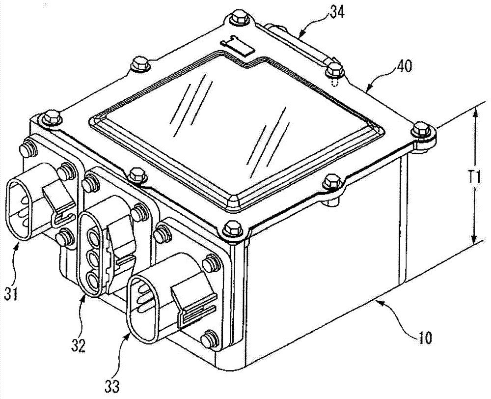
[0077] Below, based on Figure 1 to Figure 5 The electrical junction box of the present invention will be described. According to the electrical junction box of the present invention, even when the shape of the shielding box is square, there is no misinstallation of the junction box, no waste of space and no increase in weight, the moment of inertia at the time of vibration can be reduced, and the Optimal positioning of junction boxes.

[0078]

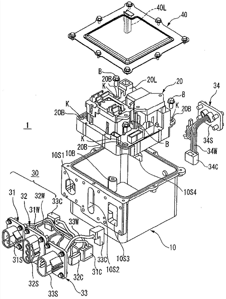
[0079] figure 1 It is an exploded perspective view of the electrical junction box of the present invention.

[0080] exist figure 1 Among them, the electrical junction box 1 of the present invention has: a shielding box 10, a junction box 20 accommodated in the shielding box 10, and an electrical component such as a fuse and a relay for connecting the electrical components such as a fuse and a relay in the junction box 20 to an external storage battery and inverter. The in-vehicle wiring 30 electrically connected to electronic...


PUM


Abstract

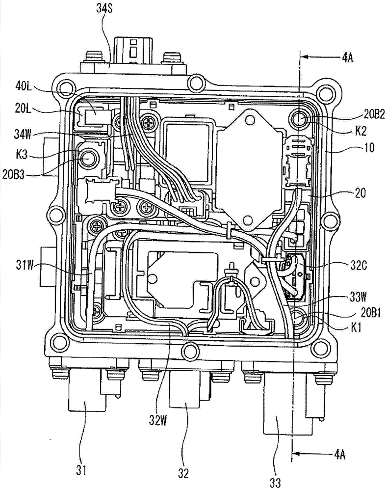
The invention relates to an electric junction box which can prevent mounting error of a distribution box on condition that the shape of a shielding box is square. The electric junction box is provided with the components of: the shielding box (10) which is internally provided with an accommodating space, the distribution box (20) which is accommodated in the accommodating space, and a box cover (40) which covers the space of the shielding box. The distribution box side is provided with a distribution box side interlock connector (20L). The box cover side is provided with a box cover side interlock connector (40L). The shielding box side is provided with three bolt fastening bosses (10B1, 10B2,10B3). The distribution box side is provided with gasket-equipped bolt holes (20B1,20B2,20B3) at the positions which correspond with the bolt fastening bosses. Furthermore the three bolt fastening bosses (10B1,10B2,10B3) are respectively arranged at the positions which are not in left-and-right symmetry in the shielding box (10).

Description

technical field [0001] The present invention relates to an electrical junction box for accommodating a junction box (junction box) in which electrical components such as fuses and relays are installed, and particularly relates to an electrical junction box that realizes optimal positioning of the junction box. Background technique [0002] Conventionally, electric vehicles including hybrid vehicles have mounted electrical junction boxes to electrically connect a storage battery, an inverter, and the like (see Patent Document 1). [0003] The electrical junction box as the object of the present invention contains: a shielding box, a junction box accommodated in the shielding box, and electrical components such as fuses and relays in the junction box and electronic components such as external batteries and inverters. In-vehicle wiring to which the device is electrically connected. [0004] 〈Existing electrical junction box〉 [0005] Image 6 It is a perspective view of an ex...

Claims


Application Information

Patent Timeline
Patent Type & Authority Applications(China)
IPC IPC(8): H02G3/14
Inventor 池田智洋酒井太志
Owner YAZAKI CORP
Learn More