Method and auxiliary device for positioning fault point of optical cable

A positioning method and positioning assistance technology, applied in the direction of transmission monitoring/testing/fault measurement system, etc., can solve the problems of uncertain geographical laying position, undetermined geographical location, bending, etc., achieve simple principle and structure, save processing time, The effect of improving maintenance ability

Active Publication Date: 2014-05-21
ZHONGSHAN SHUIMU GUANGHUA ELECTRONICS INFORMATION TECH CO LTD
View PDF4 Cites 9 Cited by
  • Summary
  • Abstract
  • Description
  • Claims
  • Application Information

AI Technical Summary

Problems solved by technology

[0002] In the geographical location of optical cable faults, accurately locating optical cable faults to a small geographical area is the most important task in the handling of optical cable faults. It is laid completely according to the design route, including bending or bending due to terrain, making its specific geographical laying position uncertain, especially in the later period due to external factors (such as when urban reconstruction needs to move optical cables or when optical cables are extended), so that not only cannot Determine its specific geographic location, and the length of the optical cable between each splice box cannot be determined), resulting in the later failure of the optical cable, it can only be known that the fault point of the optical cable appears relative to the origin of the actual optical cable (this origin is artificially set in the actual Any position of the optical cable) makes it more difficult to determine the geographical location of the cable fault point, which brings great difficulty to the real-time repair of the optical cable

Method used


Image

  • Method and auxiliary device for positioning fault point of optical cable
  • Method and auxiliary device for positioning fault point of optical cable

Examples


Embodiment Construction

[0017] The present invention will be further described in detail below in conjunction with the accompanying drawings, but not as any limitation to the present invention.

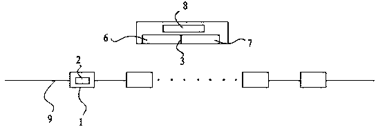
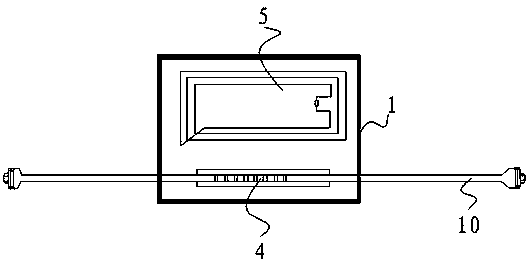
[0018] A method for locating a fault point of an optical cable according to the present invention is provided with a signal device on each joint box of the optical cable, and the signal device, the signal scanning device and the monitoring fiber core in the optical cable form an optical cable fault point positioning system, and a GIS system is used to locate the fault point of the optical cable. Accurately display the fault point to the geographic location.

[0019] The optical cable fault location system includes two sets of subsystems: one is the actual length display system of the optical cable, and the other is the actual geographical location display system of the optical cable; On the core, according to the signal device and the monitoring fiber core, the segmented display of the actual length of the o...


PUM


Abstract

The invention discloses a method for positioning a fault point of an optical cable. A signal device is arranged on each connector box of the optical cable. The signal devices, a signal scanning device and a monitoring fiber core in the optical cable form an optical cable fault point positioning system. The geographical position of the fault point is accurately displayed by using a geographic information system (GIS). The method for positioning the fault point of the optical cable can accurately and geographically locate an optical cable fault based on optical cable fault positioning technology (converting a one dimensional characteristic of the fault point of the optical cable to a confirmable two dimensional characteristic), improves running maintenance capability of the optical cable, and saves processing time of the optical cable fault. Furthermore, the method for positioning the fault point of the optical cable is simple in principle and structure, and convenient to implement, and not only can be used in an optical cable on-line monitoring system, but also can be used in an optical cable fault positioning system, an optical cable daily maintenance management system and an environment temperature monitoring system.

Description

technical field [0001] The invention relates to a method for locating a fault point of an optical cable and an auxiliary device, belonging to the technical field of optical cable maintenance. Background technique [0002] In the geographical location of optical cable faults, accurately locating optical cable faults to a small geographical area is the most important task in the handling of optical cable faults. It is laid completely according to the design route, including bending or bending due to terrain, making its specific geographical laying position uncertain, especially in the later period due to external factors (such as when urban reconstruction needs to move optical cables or when optical cables are extended), so that not only cannot Determine its specific geographic location, and the length of the optical cable between each splice box cannot be determined), resulting in the later failure of the optical cable, it can only be known that the fault point of the optical...

Claims


Application Information

Patent Timeline
Patent Type & Authority Applications(China)
IPC IPC(8): H04B10/07
Inventor 李华敏
Owner ZHONGSHAN SHUIMU GUANGHUA ELECTRONICS INFORMATION TECH CO LTD
Why Eureka
Try Eureka