Robotic bionic wrist joint and its structure optimization method

An optimization method and wrist joint technology, applied in the direction of manipulators, manufacturing tools, joints, etc., can solve the problems that the three-dimensional movement of the motion platform cannot be realized, and the motion cannot be realized, so as to simplify the kinematics and dynamics model, improve the range of motion, The effect of simple structure

An optimization method and wrist joint technology, applied in the direction of manipulators, manufacturing tools, joints, etc., can solve the problems that the three-dimensional movement of the motion platform cannot be realized, and the motion cannot be realized, so as to simplify the kinematics and dynamics model, improve the range of motion, The effect of simple structure

CN103831839BInactive Publication Date: 2016-01-20NANJING UNIV OF AERONAUTICS & ASTRONAUTICS

Image

  • Robotic bionic wrist joint and its structure optimization method
  • Robotic bionic wrist joint and its structure optimization method
  • Robotic bionic wrist joint and its structure optimization method

Examples


Embodiment Construction

[0024] specific implementation plan

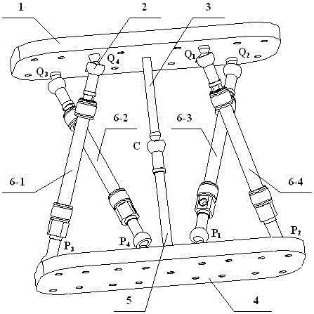
[0025] like image 3 As shown, a bionic wrist joint is now provided, including a motion platform 1, a spherical pair 2 (Q 1 , Q 2 , Q 3 ,P 1 ,P 2 ,P 3 ,P 4 , C), composed of upper fixed rod 3, fixed platform 4, lower fixed rod 5 and pneumatic artificial muscle 6.

[0026] Each driver is composed of a pneumatic artificial muscle and two spherical pairs, the spherical pair is connected with the pneumatic artificial muscle through threads, and the spherical pairs at both ends are connected to the moving platform and the fixed platform. Keep Spherical Vice Q 1 , Q 2 , Q 3 , Q 4 The plane where the center is located is parallel to the motion platform, and the spherical pair P 1 ,P 2 ,P 3 ,P 4 The platform on which the center is located is parallel to the fixed platform. in Q 1 , Q 2 , Q 3 , Q 4 The plane composed of the center (as the motion plane) establishes the motion coordinate system A, and the spherical pair P 1 ,P 2...


PUM


Abstract

The invention relates to a robot bionic wrist joint and a structure optimization method of the robot bionic wrist joint, and belongs to the field of robots. The robot bionic wrist joint comprises a motion platform (1), a spherical pair (2), an upper fixing rod (3), a fixed platform (4), a lower fixing rod (5) and pneumatic manual muscles (6). The upper fixing rod is connected with the motion platform, the lower fixing rod is connected with the fixed platform, and meanwhile an upper connecting rod and a lower connecting rod are connected through the spherical pair. The four peripheral pneumatic manual muscles on the periphery are divided into two sets, the pneumatic manual muscles in each set are distributed in a crossed mode, and the four pneumatic manual muscles act on each other to jointly control the motion platform to move relative to the fixed platform. The robot bionic wrist joint has the advantages of being compact in structure, large in rotation control range, high in compliance and the like, and has the wide application prospect.

Description

technical field [0001] The invention relates to a robot bionic wrist joint and a structure optimization method thereof, in particular to a bionic robot wrist joint driven by pneumatic artificial muscles. Background technique [0002] The wrist joint is an important part of the connection between the robot arm and the palm. Its function is to realize the three-dimensional rotation of the wrist joint in three-dimensional space, mainly including the flexion, extension, adduction and abduction of the wrist joint. [0003] At present, the mainstream wrist joint mainly realizes three-degree-of-freedom rotation through a complex mechanical structure, and the movement of each part is driven by a motor, and the stiffness of the wrist joint is high. For example, a robot wrist joint invented by Zhan Jianming and others (Patent No. 201310199119.1). These traditional wrist joints bring some unfavorable factors: the driving muscles of the wrist joint usually include rack and pinion trans...

Claims


Application Information

Patent Timeline
20 Jan 2016
Publication
CN103831839B
IPC
B25J17/00
Inventors
刘凯; 顾宝彤