Touch control device and electronic equipment

A touch device and electronic equipment technology, applied in the field of electronics, can solve the problem of low detection accuracy of touch operation, and achieve the effects of avoiding detection dead spots, high detection accuracy and increasing scanning density

Inactive Publication Date: 2014-06-04
LENOVO (BEIJING) CO LTD
View PDF5 Cites 6 Cited by
  • Summary
  • Abstract
  • Description
  • Claims
  • Application Information

AI Technical Summary

Problems solved by technology

[0013] Embodiments of the present invention provide a touch control device and electronic equipment, which are

Method used


Image

  • Touch control device and electronic equipment
  • Touch control device and electronic equipment
  • Touch control device and electronic equipment

Examples


Embodiment 1

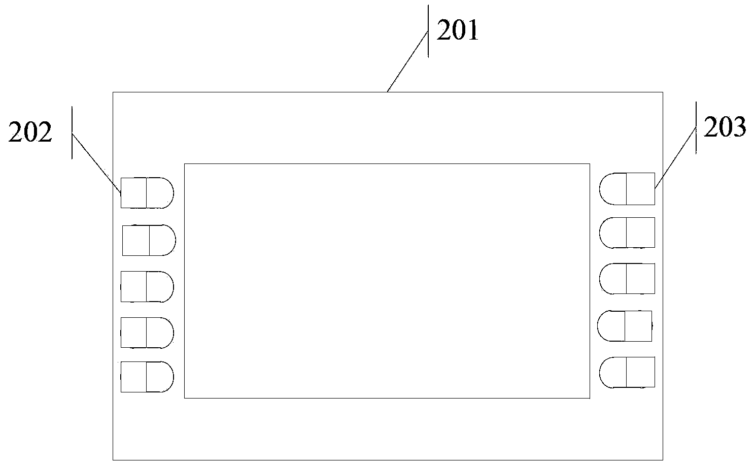
[0065] Embodiment 1 of this application provides a touch device, please refer to figure 2 , the touch device specifically includes:

[0066] Touch module 201;

[0067] The first infrared detection module 202 is arranged on the first edge of the touch module 201, wherein the first infrared detection module 202 can emit first infrared light in a first direction to the surface of the touch module 201 Signal;

[0068] The second infrared detection module 203 is arranged on the second edge of the touch module 201, wherein the first edge is opposite to the second edge, and the second infrared detection module 203 can provide the touch module with 201 The surface emits a second infrared light signal whose direction is the second direction;

[0069] Wherein, in the case that the first infrared light signal and the second infrared light signal are not blocked, the first infrared light signal is received by the second infrared detection module 203, and the second infrared light sign...

Embodiment 2

[0089] Based on the same inventive concept, Embodiment 2 of this application provides an electronic device, please refer to Figure 4 , the electronic device specifically includes the following structure:

[0090] Housing 401;

[0091] The touch module 201 is arranged on the surface of the casing 401;

[0092] The first infrared detection module 202 is arranged on the first edge of the touch module 201, wherein the first infrared detection module 202 can emit first infrared light in a first direction to the surface of the touch module 201 Signal;

[0093] The second infrared detection module 203 is arranged on the second edge of the touch module 201, wherein the first edge is opposite to the second edge, and the second infrared detection module 203 can provide the touch module with 201 The surface emits a second infrared light signal whose direction is the second direction;

[0094] Wherein, in the case that the first infrared light signal and the second infrared light sig...


PUM


Abstract

The invention discloses a touch control device and electronic equipment. The touch control device comprises a touch control module, a first infrared detection module which is arranged on the first edge of the touch control module and capable of emitting a first infrared light signal in the first direction to the surface of the touch control module, and a second infrared detection module arranged on the second edge of the touch control module, wherein the first edge is opposite to the second edge, and the second infrared detection module is capable of emitting a second infrared light signal in the second direction to the surface of the touch control module. When first touch control operation generated by a first touch control body exists in a first area of the surface of the touch control module, the touch control module determines a first shielded area formed due to the fact that the first infrared light signal and the second infrared light signal are shielded by the first touch control body through detection, and determines the first touch control position of a first touch control point, corresponding to the first touch control operation, on the surface of the touch control module based on the first shielded area.

Description

technical field [0001] The present invention relates to the field of electronic technology, in particular to a touch device and electronic equipment. Background technique [0002] With the development of global information technology, electronic equipment products have completely penetrated into people's lives. Many electronic equipment products, such as notebooks, mobile phones, PAD, etc., and with the development of electronic equipment, more and more input devices have been produced, such as: mouse, keyboard, touch unit, etc. Among them, the touch unit is due to the operation Convenience has been welcomed by more and more users. [0003] In the existing technology, such as figure 1 As shown, the touch unit may generally include the following structure: [0004] touch module 101; [0005] The circuit board frame 102 is arranged on the outside of the touch module 101; [0006] The first infrared emitter 103 is arranged on the first side of the circuit board frame 102, ...

Claims


Application Information

Patent Timeline
IPC IPC(8): G06F3/042
Inventor 穆佳昆
Owner LENOVO (BEIJING) CO LTD
Why Eureka
Try Eureka