Portable terminal

A portable terminal and frame technology, applied to antennas, antenna parts, antenna equipment with additional functions, etc., can solve problems such as antenna short circuit, achieve miniaturization design, improve signal quality, and solve the effect of antenna short circuit

Active Publication Date: 2014-06-04
LENOVO (BEIJING) CO LTD
View PDF6 Cites 4 Cited by
  • Summary
  • Abstract
  • Description
  • Claims
  • Application Information

AI Technical Summary

Problems solved by technology

[0004] In view of the above situation, the present invention provides a portable terminal, which can not only realize ultra-thin and miniaturized design, but also solve the problem that the antenna is easily short-circuited when the user holds the portable terminal, and significantly improves the signal quality

Method used


Image

  • Portable terminal
  • Portable terminal
  • Portable terminal

Examples


Embodiment Construction

[0023] Hereinafter, a portable terminal according to an embodiment of the present invention will be described in detail with reference to the accompanying drawings.

[0024] It should be noted that, in order to describe the portable terminal of the embodiment of the present invention, a schematic diagram is shown Figure 1-Figure 4 . Figure 1-Figure 4 It is to be considered in all respects as illustrative rather than restrictive. also, Figure 1-Figure 4 The dimensions and proportions of the components in are merely exemplary, and are not drawn according to their actual dimensions and proportions.

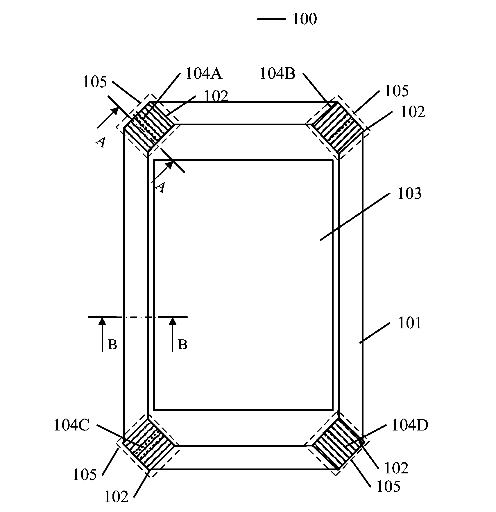
[0025] First, refer to figure 1 , figure 1 is a front view illustrating a portable terminal according to an embodiment of the present invention. Such as figure 1 As shown, the portable terminal 100 of the embodiment of the present invention includes a first frame body 101 and a second frame body 102 . exist figure 1 In , the first frame body 101 is shown as a blank frame b...


PUM


Abstract

The invention provides a portable terminal. The portable terminal is characterized in that the portable terminal comprises a first frame body and a second frame body; the first frame body is used for an antenna unit of the portable terminal; the first partial area of the first frame body is provided a clearance; the partial area with the clearance is covered with the second frame body.

Description

technical field [0001] The present invention relates to the field of portable terminals. Background technique [0002] In recent years, with the pursuit of miniaturization, ultra-thinness and metal texture of portable terminals, the traditional antenna design is facing great challenges. Especially in the case of a metal frame, it is difficult to achieve ultra-thin traditional antenna design. [0003] In this regard, there is a method in the prior art, which uses the metal frame of the portable terminal as the antenna, which helps to solve the problem of the harsh environment of the built-in antenna. However, since the user easily touches the gap of the metal frame when holding the portable terminal, a short circuit is caused, thereby severely degrading the signal. Contents of the invention [0004] In view of the above situation, the present invention provides a portable terminal, which can not only realize ultra-thin and miniaturized design, but also solve the problem t...

Claims


Application Information

Patent Timeline
Patent Type & Authority Applications(China)
IPC IPC(8): H01Q1/44H01Q1/22
CPCH01Q1/243
Inventor 崔斌
Owner LENOVO (BEIJING) CO LTD
Why Eureka
Try Eureka