
Wire binding support integrated on bottom board

A wire-binding bracket and bottom plate technology, which is applied in the field of wire-binding brackets, can solve problems such as the inconvenient installation of the wire-binding bracket for fixing incoming and outgoing cables, and the effective installation space occupied by the wire-binding bracket.

Inactive Publication Date: 2014-06-04
LUOYANG XINSILU ELECTRIC
View PDF6 Cites 0 Cited by
  • Summary
  • Abstract
  • Description
  • Claims
  • Application Information

AI Technical Summary

Problems solved by technology

However, the wire-binding bracket occupies the effective installation space in the cabinet, and the wire-binding bracket is installed on a vertical surface. If there are many electrical components in the cabinet and the installation space is tight, the installation of the wire-binding bracket and the fixing of the incoming and outgoing cables are very difficult. inconvenient

Method used


Image

  • Wire binding support integrated on bottom board
  • Wire binding support integrated on bottom board
  • Wire binding support integrated on bottom board

Examples


Embodiment Construction

[0021] In order to further explain the technical means and effects of the present invention to achieve the intended purpose of the invention, the specific implementation, structure, and structure of the wire binding bracket integrated on the bottom plate proposed in accordance with the present invention will be given with reference to the accompanying drawings and preferred embodiments. The characteristics and effects are described in detail later.

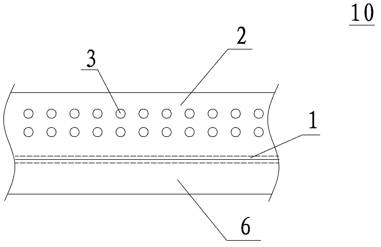
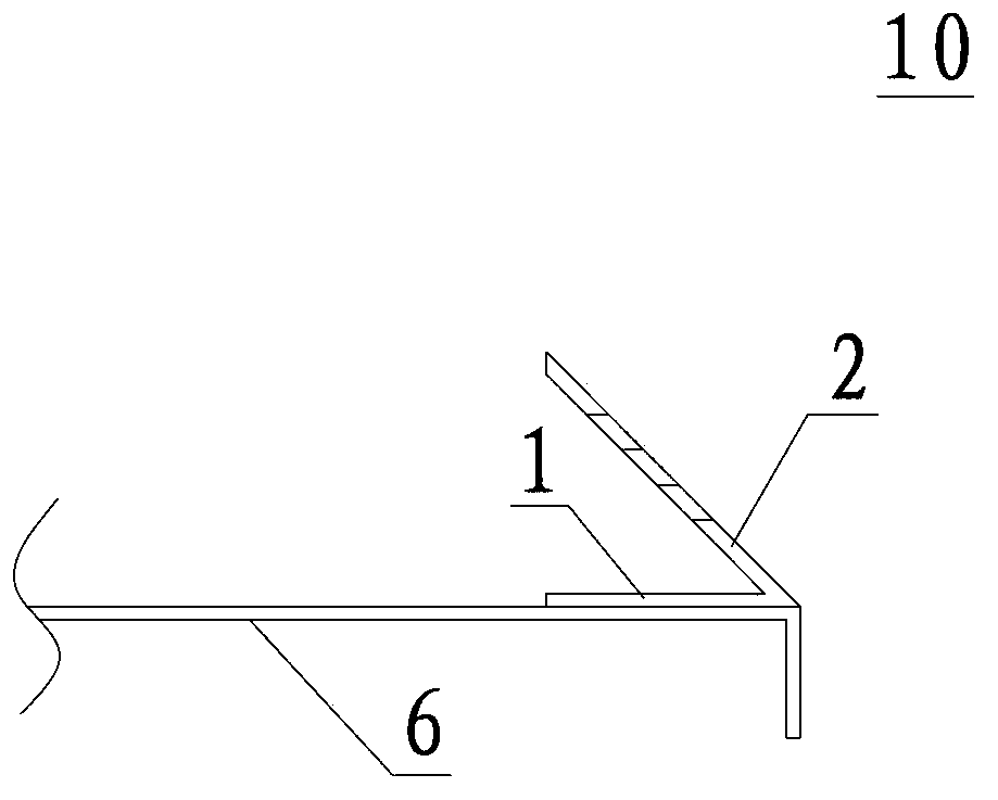
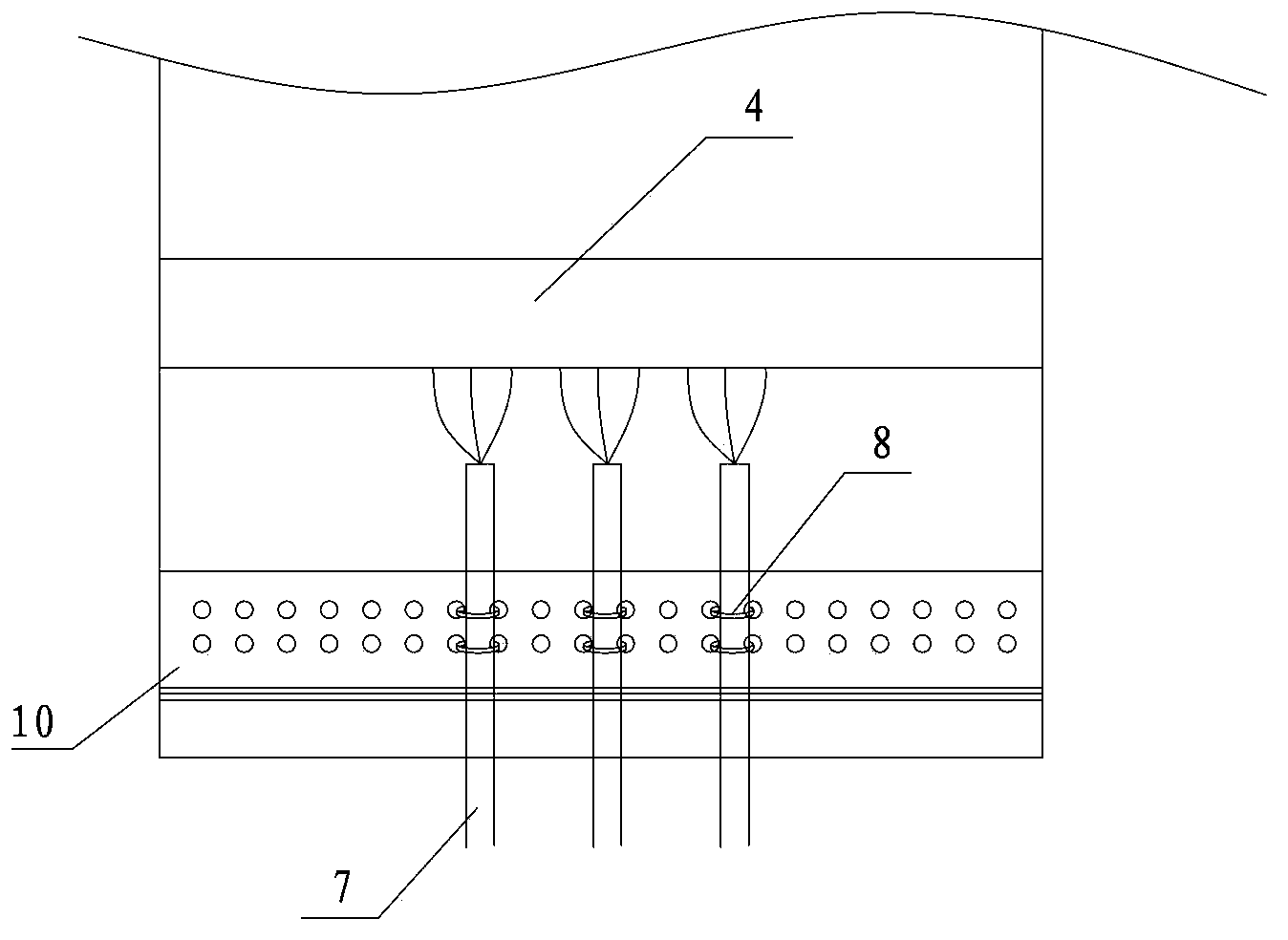
[0022] See Figure 1A with Figure 1B , Are respectively the front view and side view of the wire binding bracket integrated on the bottom plate of the present invention. The wire binding bracket 10 includes a bottom surface 1 and a front surface 2 intersecting the bottom surface. The bottom surface 1 and the front surface 2 have an angle of less than 90° The included angle, that is, the wire-binding bracket 10 has a V-shaped structure, and the punching holes 3 are evenly arranged on the front side 2 of the wire-binding bracket as fixi...


PUM

PropertyMeasurementUnit
Angleaaaaaaaaaa
Widthaaaaaaaaaa

Abstract

The invention relates to a wire binding support integrated on a bottom board. The wire binding support is of a V-shaped structure and comprises the bottom face and the front face intersected by the bottom face. An included angle smaller than 90 degrees is formed between the bottom face and the front face. Punched holes are evenly formed in the front face. The wire binding support is fixed to the bottom board. The wire binding support is integrated on the bottom board of an electrical control cabinet, so that effective installation space inside the cabinet is saved, elements are installed more compactly, meanwhile, a slope mode is adopted by the wire binding support, and therefore wire binding operation is facilitated.

Description

Technical field [0001] The invention belongs to the field of low-voltage power distribution, and mainly relates to a wire binding bracket integrated on a bottom plate in an electric control cabinet. Background technique [0002] The incoming and outgoing cables in the electrical control cabinet need to be bundled and fixed. The current method is to install a helper bracket at the lower part of the terminal block to fix the cables. However, the wire binding bracket occupies the effective installation space in the cabinet, and the wire binding bracket is installed on a vertical surface. If there are many electrical components in the cabinet and the installation space is tight, the installation of the wire binding bracket and the fixing of the incoming and outgoing cables are very difficult. inconvenient. Summary of the invention [0003] The purpose of the present invention is to provide a wire tie bracket integrated on the bottom plate to save effective installation space in the c...

Claims


Application Information

Patent Timeline
IPC IPC(8): H02B1/01
Inventor 胡洛夷李志鹏李春
Owner LUOYANG XINSILU ELECTRIC
Learn More