Magnetic sensor element and magnetic sensor using the same

a technology of magnetic sensor and magnetic sensor, which is applied in the direction of magnetic measurement, instruments, measurement devices, etc., can solve the problems of difficult to reduce and achieve the reduction of the size and thickness of the magnetic sensor itself, compact installation, and the effect of reducing the size and thickness of the package itsel

Active Publication Date: 2009-10-01
CITIZEN ELECTRONICS CO LTD
View PDF3 Cites 16 Cited by
  • Summary
  • Abstract
  • Description
  • Claims
  • Application Information

AI Technical Summary

Benefits of technology

[0011]In the magnetic sensor element of the present invention, since the exciting pattern, the magnetic thin film pattern for detection, and the detection coil pattern are disposed on the substrate, the magnetic sensor element can be formed into a flat shape, and the length of the generated magnetic field is short in a long axis direction. Therefore, the size and thickness of the magnetic sensor element itself can be reduced.
[0012]In the magnetic sensor of the present invention, the above magnetic sensor elements can be compactly installed in the package of the magnetic sensor. Therefore, the size and thickness of the package itself can be reduced.

Problems solved by technology

Therefore, disadvantageously, it is difficult to reduce the size and thickness of the magnetic sensor.

Method used


Image

  • Magnetic sensor element and magnetic sensor using the same
  • Magnetic sensor element and magnetic sensor using the same
  • Magnetic sensor element and magnetic sensor using the same

Examples


first embodiment

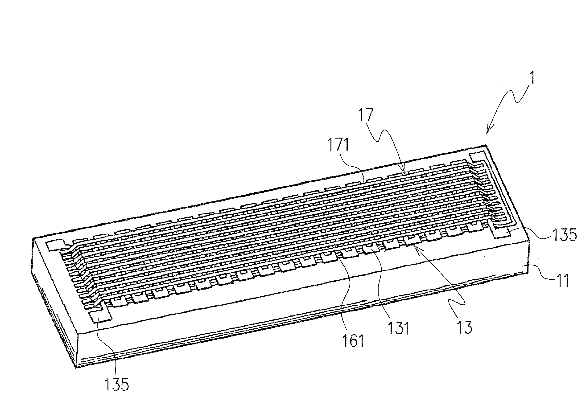
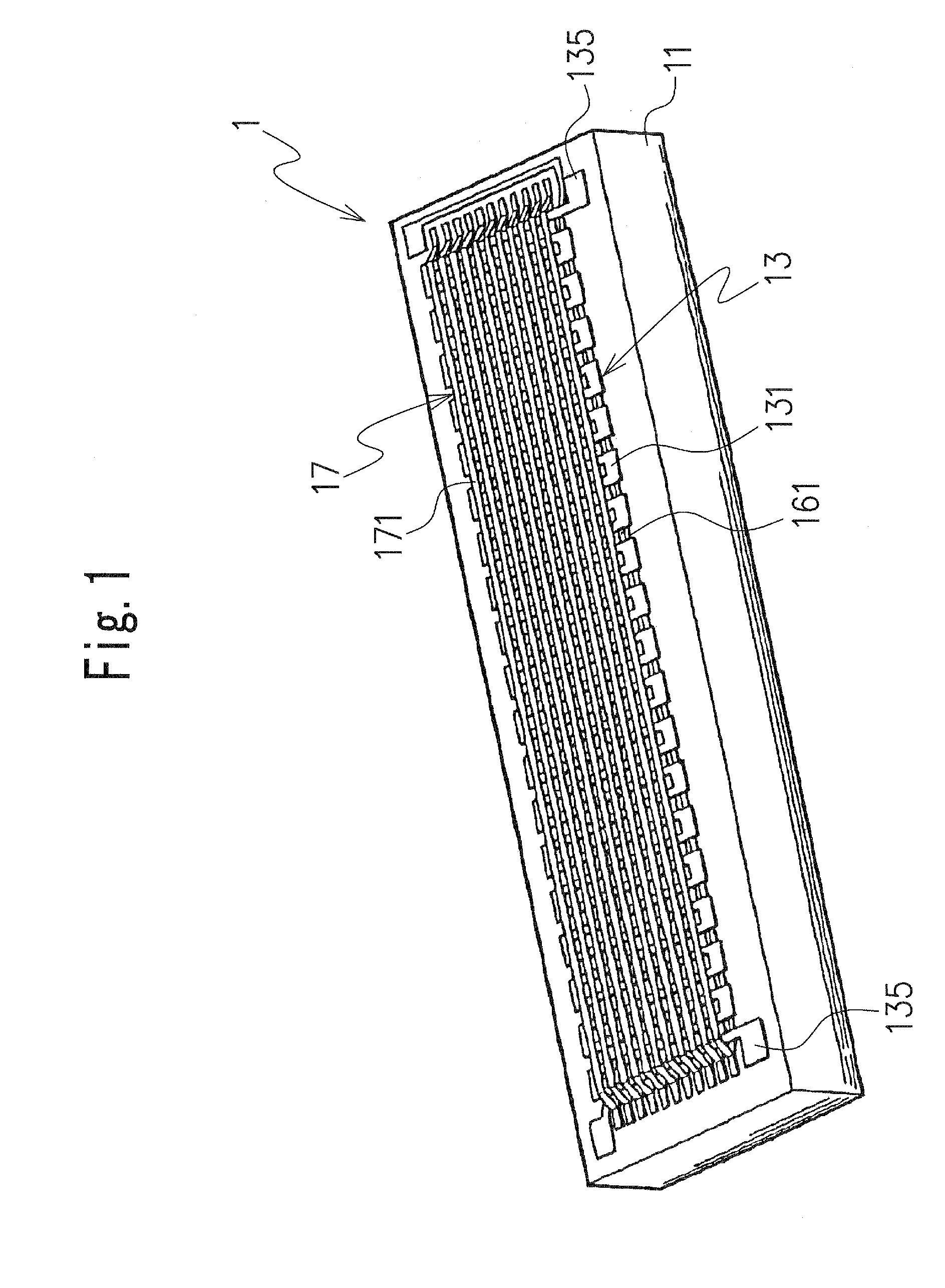
[0024]FIGS. 1 to 4 show a first embodiment of a magnetic sensor element according to the present invention. The magnetic sensor element in the first embodiment is, for example, a fluxgate magnetic sensor element 1 and includes, for example, a rectangular solid-shaped substrate 11 having a small thickness, as shown in FIGS. 1 and 3. The substrate 11 is made of an insulating material such as glass.

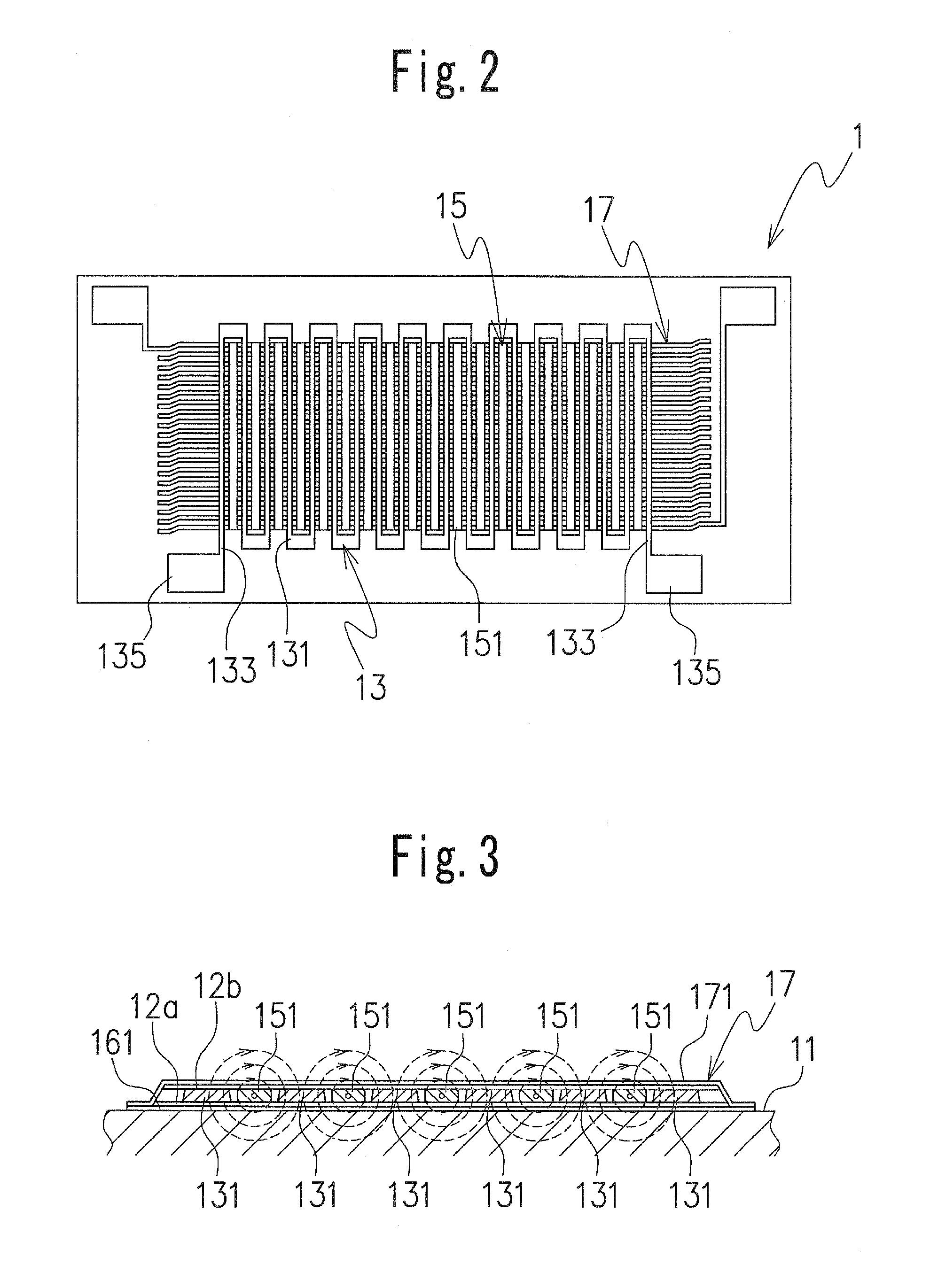
[0025]An exciting pattern 13 that generates a magnetic field, a magnetic thin film pattern 15 for detection that is disposed adjacent to the exciting pattern, and a detection coil pattern 17 that is disposed adjacent to the magnetic thin film pattern 15 for detection are disposed on the substrate 11. In particular, the exciting pattern 13, the magnetic thin film pattern 15 for detection, and the detection coil pattern 17 described above are disposed flatly on the substrate 11.

[0026]As shown in FIGS. 1 to 3, in this embodiment, the magnetic thin film pattern 15 for detection includes a plural...

second embodiment

[0042]FIGS. 6A and 6B show a second embodiment of the magnetic sensor element according to the present invention.

[0043]In the first embodiment described above, the fluxgate magnetic sensor element 1 is formed by disposing the single-layer exciting pattern 13 and the single-layer magnetic thin film pattern 15 for detection so as to be arranged alternately in the left-right direction on the substrate 11. In the second embodiment, a fluxgate magnetic sensor element 1′ is formed by vertically arranging the exciting pattern 13 and the magnetic thin film pattern 15 for detection. In this case, any of the patterns may be placed above the other pattern. As shown in the illustrated example, the magnetic thin film pattern 15 for detection may be disposed on opposite vertical sides of the exciting pattern 13. With such a configuration, the sensitivity to magnetism is expected to be further improved, and the current consumption is expected to be further reduced. Not only the magnetic thin film ...


PUM


Abstract

The present invention provides a fluxgate magnetic sensor element which includes: a substrate; an exciting pattern which is disposed on the substrate to generate a magnetic field; a magnetic thin film pattern for detection which is disposed adjacent to the exciting pattern; and a detection coil pattern which is disposed adjacent to the magnetic thin film pattern for detection. In the magnetic sensor element, the exciting pattern, the magnetic thin film pattern for detection, and the detection coil pattern are formed on the substrate. Therefore, the magnetic sensor element can be formed into a flat shape. Moreover, since the length of the generated magnetic field is short in a long-axis direction, the size and thickness of the element itself can be reduced.

Description

TECHNICAL FIELD[0001]The present invention relates to a magnetic sensor element and to a magnetic sensor. More particularly, the invention relates to a fluxgate magnetic sensor element formed into a flat shape and to a magnetic sensor including the magnetic sensor element elements, which are orthogonally disposed.BACKGROUND ART[0002]Conventionally, as a magnetic sensor for detecting a weak magnetic field such as geomagnetism, an orthogonal fluxgate magnetic sensor is known. Examples of the orthogonal fluxgate magnetic sensor include those disclosed in Japanese Patent Application Laid-Open Nos. 2005-114489, 2004-271481, 2004-198379, and 2004-184098.[0003]Such an orthogonal fluxgate magnetic sensor comprises a magnetic sensor element including a conductive body, a magnetic body disposed around the conductive body, and a detection coil wound around the magnetic body.[0004]However, the orthogonal fluxgate magnetic sensor having the structure described above has problems in that it is di...

Claims


Application Information

Patent Timeline
Patent Type & Authority Applications(United States)
IPC IPC(8): G01R33/04
CPCG01R33/05G01R33/04
Inventor HASUNUMA, TAKASHI
Owner CITIZEN ELECTRONICS CO LTD
Why Eureka
Try Eureka