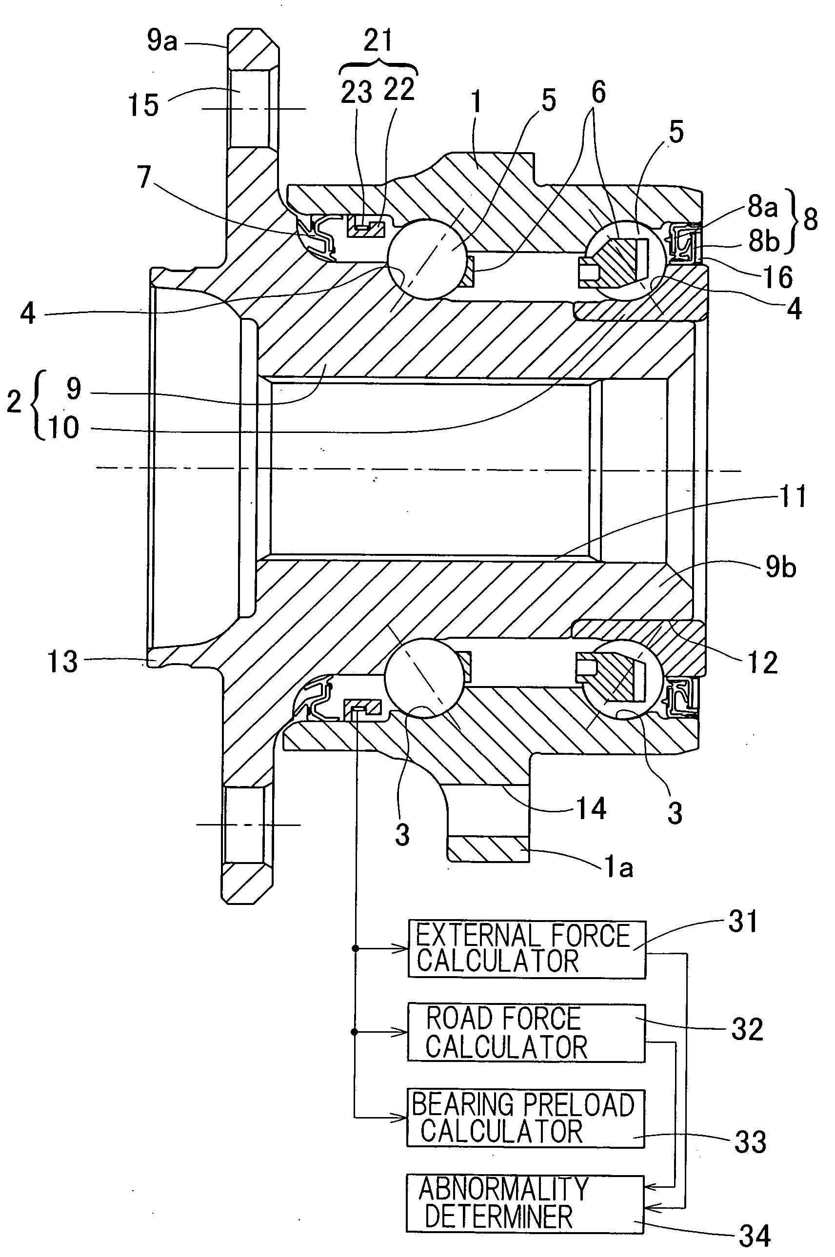
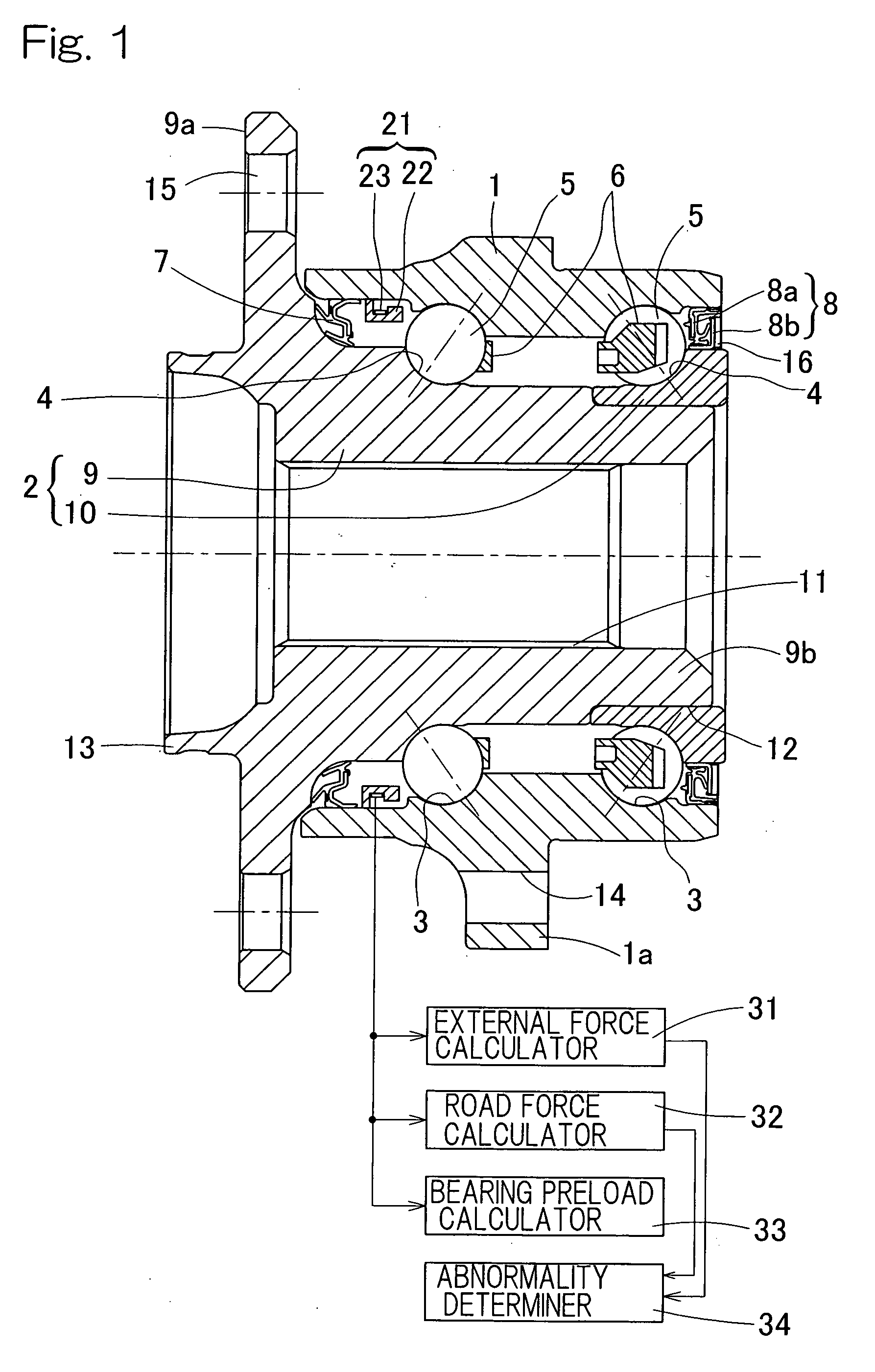
Sensor-equipped bearing for wheel
a technology of bearings and wheels, applied in the direction of force sensors, mechanical equipment, transportation and packaging, etc., can solve the problems of ring member strain and deformation, and achieve the effects of reducing cost, excellent mass productivity, and low cos
- Summary
- Abstract
- Description
- Claims
- Application Information
AI Technical Summary
Benefits of technology
Problems solved by technology
Method used
Image
Examples
second embodiment
[0151]A third preferred embodiment of the present invention will be described with particular reference to FIGS. 7 to 9A, 9B. In this embodiment, the description for the structure common to the first or second embodiment is omitted.
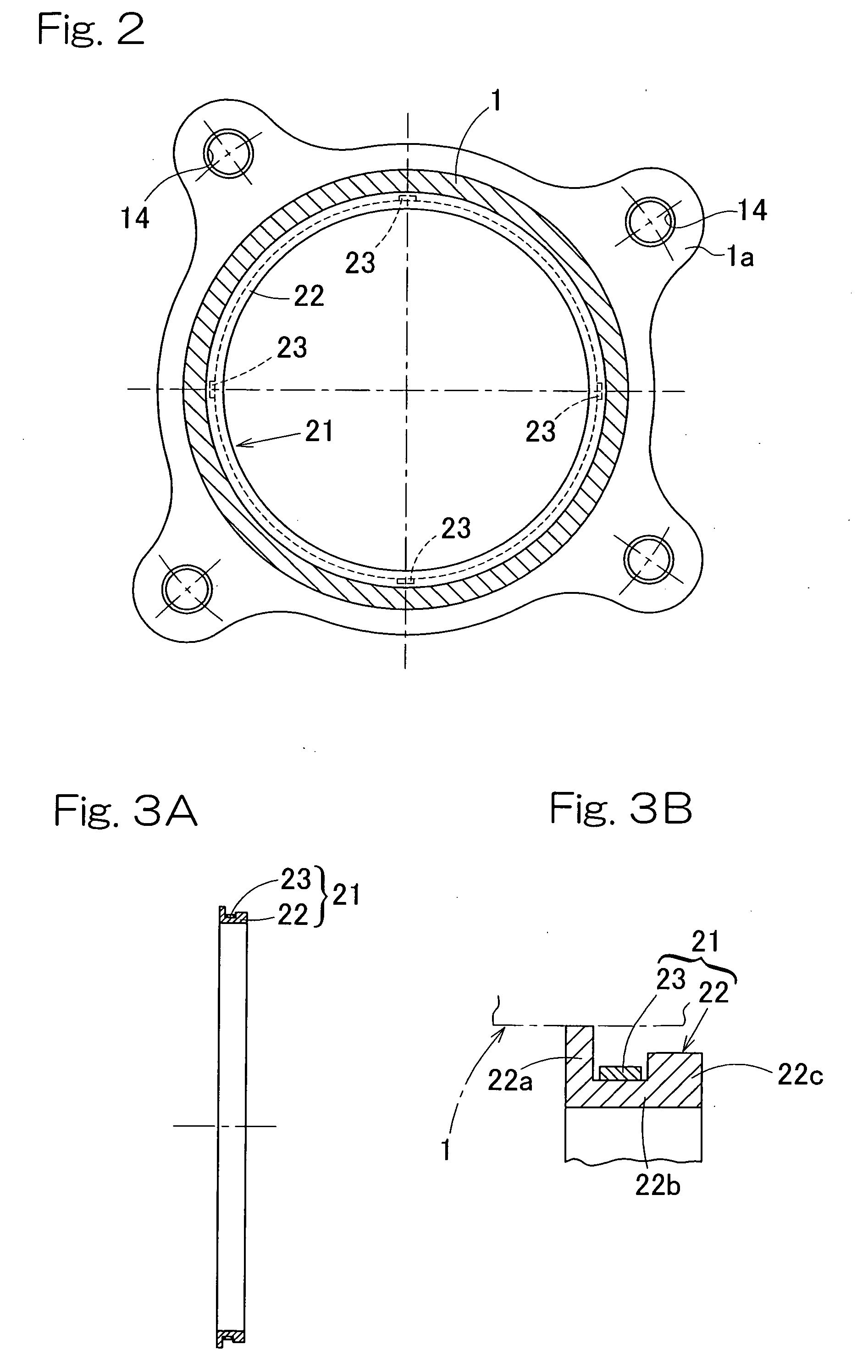
[0152]As shown in FIGS. 7 and 9B, the transverse sectional shape of the ring member 22 is represented by a grooved shape having contact ring portions 22a and 22e (the first contact ring portion 22a and a second contact ring portion 22e) in contact with the inner peripheral surface of the outer member 1 and a non-contact ring portion (a first non-contact ring portion) 22f not in contact with the inner peripheral surface of the outer member 1. The non-contact ring portion 22f forms a bottom wall portion of the grooved shape and the contact ring portions 22a and 22e form respective side wall portions on both sides of the groove shape. The contact ring portions 22a and 22e on both sides have greater wall thickness than the non-contact ring portion 22f. Here, ...
third embodiment
[0199]In this embodiment, under the effect of a load acting on the hub axle 9, the outer member 1 is deformed through the rolling elements 5 and the deformation is transmitted to the ring member 22 fitted to the end face of the outer member 1 to deform the ring member 22. In the sensor unit 21 employed in this embodiment, the contact ring portion 22g having the strain sensors 23 affixed thereto is deformed mainly according to the deformation of the outer member 1 in the axial direction. Since the contact ring portion 22h and the non-contact ring portion 22i have great wall thickness, they have high rigidity and are hard to be deformed, resulting in the axial strain in on the contact ring portion 22g having smaller wall thickness. The strain represents a transferred and enlarged radial strain on the end face of the outer member 1. Thus, similarly to the third embodiment, the strain measurement at high accuracy can be expected.
[0200]In this embodiment, as described above, the load det...
fourth embodiment
[0234]In this embodiment, under the effect of a load acting on the hub axle 9, the outer member 1 is deformed through the rolling elements 5 and the deformation is transmitted to the ring member 22 fitted to the inner peripheral surface of the outer member 1 to deform the ring member 22. In the sensor unit 21 employed in this embodiment, the contact ring portion 22g having the strain detectors 23a is deformed mainly according to the deformation of the outer member 1 in the axial direction. Since the contact ring portion 22h and the non-contact ring portion 22i have great wall thickness, those portions have high rigidity and are hard to be deformed. Therefore, the bending strain is caused on the contact ring portion 22g having smaller wall thickness. The strain represents a transferred and enlarged axial strain on the inner peripheral surface of the outer member 1, whereby, similarly to the fourth embodiment, the strain measurement at high accuracy can be expected.
[0235]In this embod...
PUM
 Abstract
Description
Claims
Application Information
 - R&D
- Intellectual Property
- Life Sciences
- Materials
- Tech Scout
- Unparalleled Data Quality
- Higher Quality Content
- 60% Fewer Hallucinations
Browse by: Latest US Patents, China's latest patents, Technical Efficacy Thesaurus, Application Domain, Technology Topic, Popular Technical Reports.
© 2025 PatSnap. All rights reserved.Legal|Privacy policy|Modern Slavery Act Transparency Statement|Sitemap|About US| Contact US: help@patsnap.com


