Nested type three-phase mixing nozzle of water, oil and gas and nozzle system with same

A mixing nozzle and nested technology, which is applied in the direction of spraying devices, liquid spraying devices, maintenance and safety accessories, etc., can solve problems such as incomplete mixing, affecting the health of workers and the environment, and complex processes, and achieve the goal of improving surface finish Effect

Active Publication Date: 2014-01-22
苏州金兆环保节能设备有限公司
View PDF8 Cites 15 Cited by
  • Summary
  • Abstract
  • Description
  • Claims
  • Application Information

AI Technical Summary

Problems solved by technology

[0003] At present, lubricants such as coolants, emulsions, or cutting oils are mostly used for lubrication and cooling of existing metal cold processing. These types of lubricants are sprayed on the processing parts in large quantities during metal processing, usually in the form of uninterrupted showering. In this way, the same cooling and lubrication are carried out in other parts that do not need cooling and lubrication, resulting in a large amount of cooling medium, causing waste, and polluting the environment
[0004] In recent years, the research on minimal quantity lubrication technology has made great progress, which has reduced the harm caused by the discharge of a large amount of cutting oil to the environment. However, in many processing processes, it is often difficult to effectively solve the cooling problem, and the minimum quantity lubrication device mainly uses compressed air. Take away the heat generated by friction and the debris generated by processing, and the air consumptio

Method used


Image

  • Nested type three-phase mixing nozzle of water, oil and gas and nozzle system with same
  • Nested type three-phase mixing nozzle of water, oil and gas and nozzle system with same
  • Nested type three-phase mixing nozzle of water, oil and gas and nozzle system with same

Examples


Embodiment Construction

[0073] Now, the present invention will be described in further detail in conjunction with the accompanying drawings and specific embodiments. These drawings are all simplified schematic diagrams, which only illustrate the basic structure of the present invention in a schematic manner, so they only show the configurations related to the present invention.

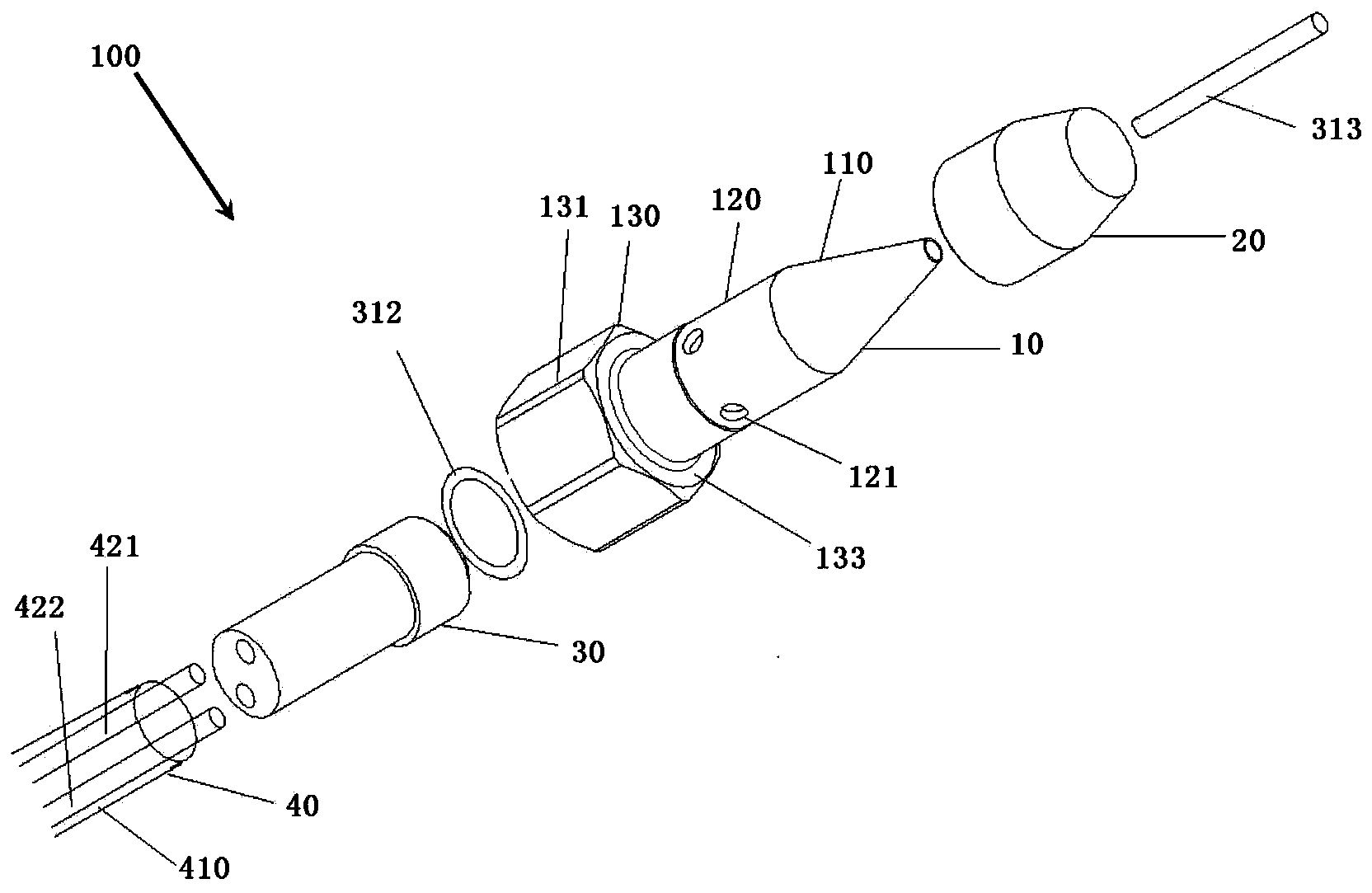
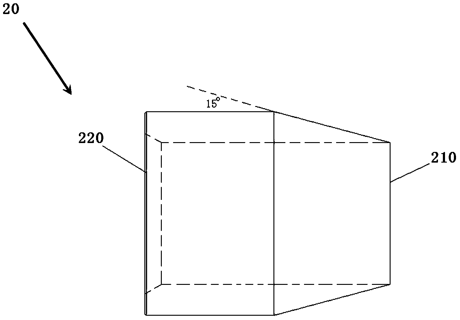
[0074] like figure 1 As shown, the present embodiment provides a nozzle system 100 including a nested water, oil and gas three-phase mixing nozzle, including a nozzle body 10 , a nesting ring 20 , a mixing chamber 30 and a gas-liquid input mechanism 40 .

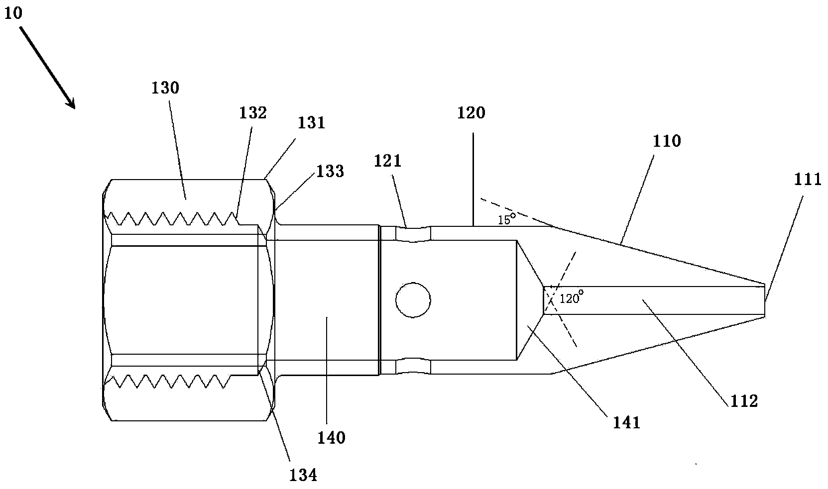
[0075] like figure 1 and 2 As shown, the nozzle body 10 includes a head 110 , a middle 120 and a bottom 130 . The head 110 of the nozzle body 10 is a cone, and the top is provided with an injection hole 111; the middle part 120 of the nozzle body 10 is a cylinder, and four air holes 121 are uniformly arranged on the cylinder; the bottom 130 of the nozzle body 10 is a ...


PUM


Abstract

The invention provides a nested type three-phase mixing nozzle of water, oil and gas. The nested type three-phase mixing nozzle comprises a nozzle body, a nesting ring and a mixing chamber, and is characterized in that the nozzle body comprises a head portion, a middle portion and a bottom, the head portion of the nozzle body is a cone, and a spray hole is formed in the top end of the head portion of the nozzle body; the middle portion of the nozzle body is a cylinder, and at least two gas holes are evenly formed in the cylinder; the bottom of the nozzle body is of a thread structure; the nesting ring and the middle portion of the nozzle body are matched to form a clearance structure; an inner chamber with the top of a cone is arranged inside the nozzle body; the mixing chamber is arranged in the inner chamber and corresponds to the position of the middle portion of the nozzle body; a fluid channel communicated with the spray hole is further formed in the top of the inner chamber. The nozzle is arranged in a metal processing lubricating device, point lubricating is achieved, the problem that gas consumption is large in existing novel metal near-dry type processing lubricating is solved, meanwhile, a power source is saved, and the advantages of saving lubricating oil and being more environmentally friendly are achieved.

Description

technical field [0001] The invention relates to a nozzle device, in particular to a nested water, oil and gas three-phase mixing nozzle and a nozzle system including the nozzle. Background technique [0002] In the field of traditional machining, metal processing usually involves cutting, grinding, drilling, tapping and other processing processes that easily cause the workpiece to heat up rapidly. This type of processing requires frictional contact between workpieces, and timely lubrication should usually be carried out. [0003] At present, lubricants such as coolants, emulsions, or cutting oils are mostly used for lubrication and cooling of existing metal cold processing. These types of lubricants are sprayed on the processing parts in large quantities during metal processing, usually in the form of uninterrupted showering. , In this way, the same cooling and lubrication are carried out in other parts that do not need cooling and lubrication, resulting in a large amount of...

Claims


Application Information

Patent Timeline
IPC IPC(8): B23Q11/10B05B7/04B05B7/24
CPCB05B7/045B23Q11/1076
Inventor 李刚吴启东张乃庆
Owner 苏州金兆环保节能设备有限公司
Why Eureka
Try Eureka