Active clamping high-gain single-stage inverter with pressure capable of being boosted

A high-gain, inverter technology, applied in the direction of conversion equipment without intermediate conversion to AC, climate sustainability, high-efficiency power electronic conversion, etc., can solve the problem of inverter DC link voltage overshoot, increase system complexity, Improve system efficiency and other issues, achieve the effects of small electromagnetic interference, optimized reverse recovery characteristics, and high energy conversion efficiency

Inactive Publication Date: 2014-06-04
QINGDAO TECHNOLOGICAL UNIVERSITY
View PDF4 Cites 2 Cited by
  • Summary
  • Abstract
  • Description
  • Claims
  • Application Information

AI Technical Summary

Problems solved by technology

[0002] The existing transformer-type Z-source inverter includes a rectifier diode, a coupled inductor, a capacitor and a three-phase voltage type bridge inverter circuit. This transformer-type Z-source inverter can pass through the duty cycle The voltage adjustment range is large, but the leakage inductance has obvious impact on the system, and the inverter DC link voltage overshoot and electromagnetic interference are serious; the soft switching technology is to solve the switching loss and The electromagnetic interference problem is a relatively mature solution, and it has been widely used in many occasions. The quasi-resonant soft-switching Z-source inverter realizes that all devices work in a soft-switching environment, and the system efficiency is ten times higher than that of hard-switching circuits. percent, but components such as auxiliary diodes add to the complexity of the system

Method used


Image

  • Active clamping high-gain single-stage inverter with pressure capable of being boosted

Examples


Embodiment

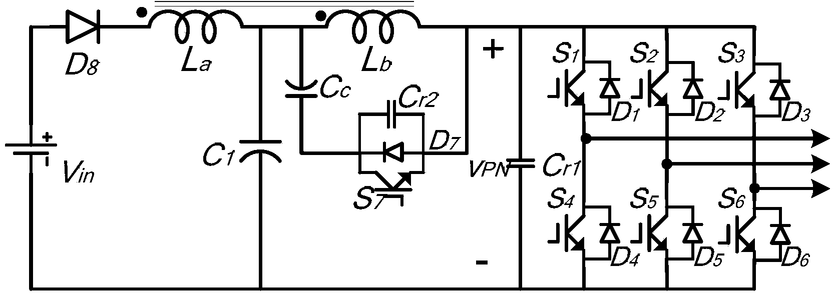
[0011] The main structure of this embodiment includes a DC power supply V in , rectifier diode D 8 , by the first winding L a with the second winding L b Composed of coupled inductors, capacitors C 1 , Auxiliary power switch tube S 7 , the anti-parallel diode D of the auxiliary power switch tube 7 , the first resonant capacitor C r1 , the second resonant capacitor C r2 , clamp capacitor C c and consists of insulated gate bipolar transistors (IGBT) s 1 ~S 6 with antiparallel diode D 1 ~D 6 Combination of three-phase voltage type bridge inverter circuit; the first winding L of the coupled inductor a with the second winding L b The terminal with the same name, the rectifier diode D 8 anode of the DC power supply V in connected to the anode of the rectifier diode D 8 The cathode of the coupled inductor with the first winding L a connected, the capacitor C 1 The positive pole of the first winding L a and the second winding L b connected to the common terminal, th...


PUM


Abstract

The invention belongs to the technical field of direct current-alternating current inversion equipment, and relates to an active clamping high-gain single-stage inverter with pressure capable of being boosted. A first winding and a second winding of a coupling inductor are dotted terminals of each other, an anode of a rectifier diode is connected with the positive pole of a direct current power supply, and the cathode of the rectifier diode is connected with the first winding of the coupling inductor. The positive pole of a capacitor is connected with the public end of the first winding and the second winding, the negative pole of the capacitor is connected with the negative pole of the direct current power supply and one end of a first resonance capacitor, and the other end of the first resonance capacitor is connected with the second winding, and the first resonance capacitor and a three-phase voltage type bridge inverter circuit are connected in parallel. An auxiliary power switching tube is respectively connected with an antiparallel diode of the auxiliary power switching tube and a second resonance capacitor in parallel and is connected with a clamping capacitor in series to form an active clamping circuit, and the active clamping circuit is connected with the second winding of the coupling inductor in parallel. The active clamping high-gain single-stage inverter is simple in structure, small in electromagnetic interference influence, few in loss, low in cost, high in energy conversion efficiency and environmentally friendly.

Description

Technical field: [0001] The invention belongs to the technical field of DC-AC inverter equipment, and relates to a DC-AC inverter, in particular to an active-clamp high-gain single-stage boostable inverter. Background technique: [0002] The existing transformer-type Z-source inverter includes a rectifier diode, a coupled inductor, a capacitor and a three-phase voltage type bridge inverter circuit. This transformer-type Z-source inverter can pass through the duty cycle The voltage adjustment range is large, but the leakage inductance has obvious impact on the system, and the inverter DC link voltage overshoot and electromagnetic interference are serious; the soft switching technology is to solve the switching loss and The electromagnetic interference problem is a relatively mature solution, and it has been widely used in many occasions. The quasi-resonant soft-switching Z-source inverter realizes that all devices work in a soft-switching environment, and the system efficienc...

Claims


Application Information

Patent Timeline
Patent Type & Authority Applications(China)
IPC IPC(8): H02M7/5387H02M3/07H02M1/32H02M1/44
CPCY02B70/10
Inventor 丁新平吴苓芝魏文健
Owner QINGDAO TECHNOLOGICAL UNIVERSITY
Why Eureka
Try Eureka