
Subframe for motor vehicle

A sub-frame and motor vehicle technology, applied in the direction of electric vehicles, electric vehicle charging technology, vehicle components, etc., can solve the problem of increasing weight

Active Publication Date: 2014-06-11
AUDI AG
View PDF8 Cites 11 Cited by
  • Summary
  • Abstract
  • Description
  • Claims
  • Application Information

AI Technical Summary

Problems solved by technology

However, this plate adds extra weight to the motor vehicle and in the prior art only has the task of increasing the torsional rigidity

Method used


Image

  • Subframe for motor vehicle
  • Subframe for motor vehicle

Examples


Embodiment Construction

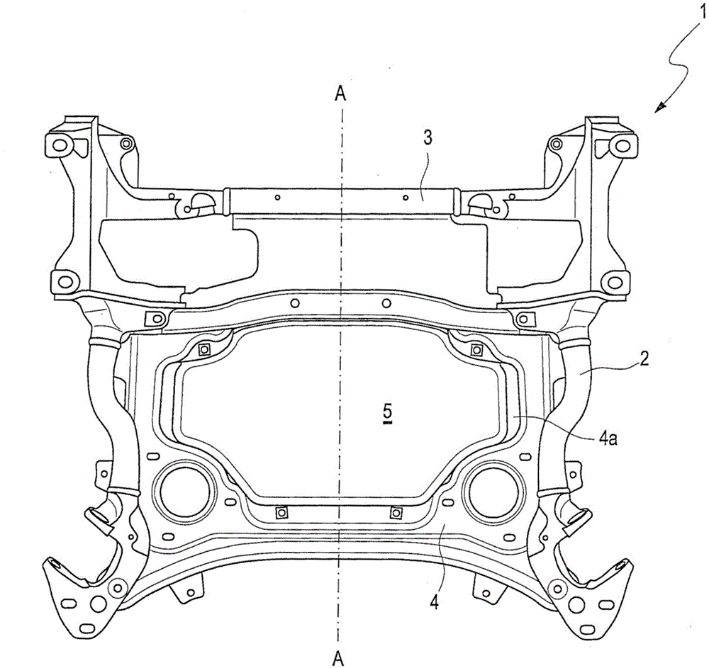
[0031] according to figure 1 A subframe 1 of a motor vehicle comprises two longitudinal brackets 2 arranged mirror-symmetrically with respect to the line of symmetry A-A and spaced apart from each other, and these longitudinal brackets are connected to each other by cross brackets 3 . The reinforcing structure 4 designed as a shear plate for increasing the torsional rigidity is arranged on the subframe 1 configured in this way. The reinforcing structure 4 has a free surface 4a in its center. Mounted on this free surface 4 a is a charging module 5 which, in the installed state, terminates as flush as possible on the bottom side with the surrounding reinforcement structure 4 . The charging module 5 thus becomes an integral part of the reinforcement structure 4 and itself contributes to the reinforcement of the subframe 1 .

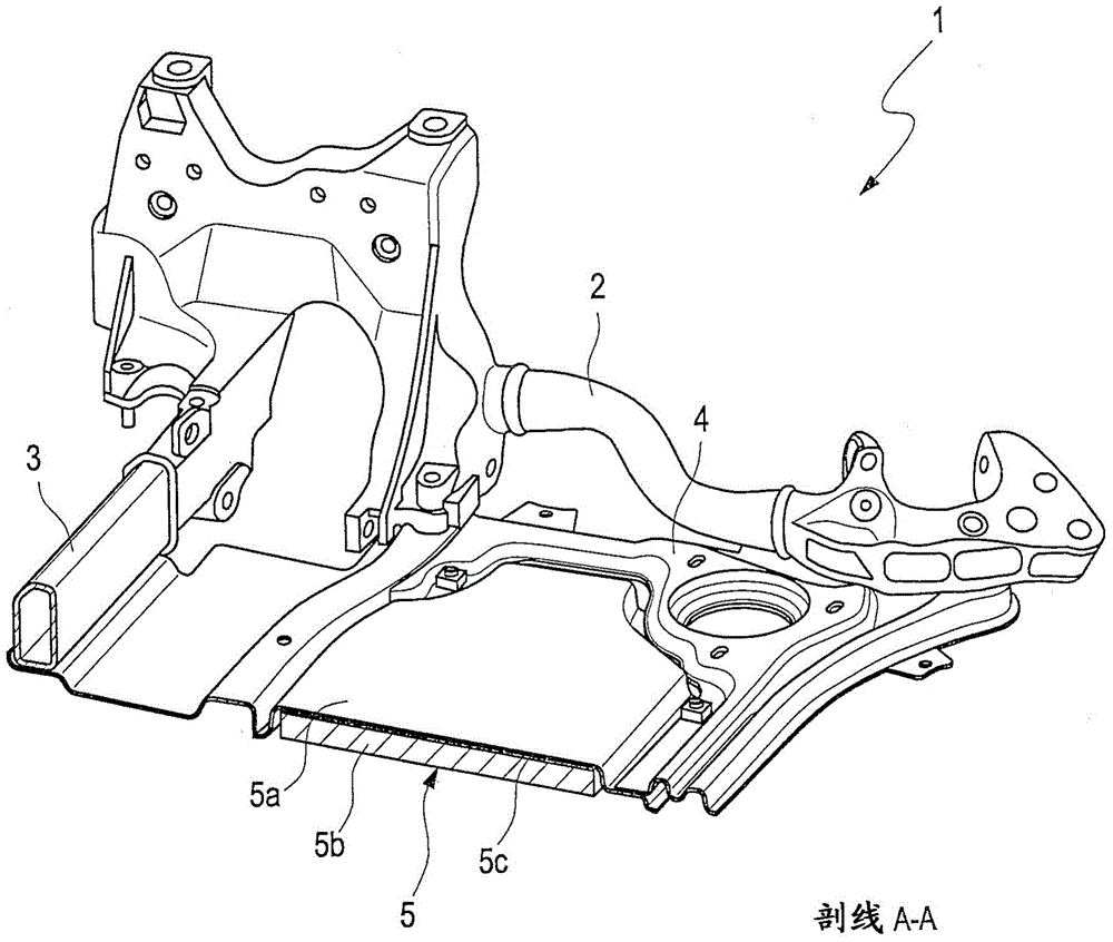
[0032] figure 2 A sectioned half of a subframe 1 with two longitudinal supports 2 and a transverse support 3 is shown. The charging module 5 includes a...


PUM


Abstract

A subframe (1) of a front or rear part of a motor vehicle includes two longitudinal members (2) arranged in spaced-apart relationship in a vehicle transverse direction and connected to one another by at least a cross member (3). A reinforcement (4) is connected to the longitudinal members and the cross member for increasing a torsion resistance of the subframe and has integrated therein a charge module (5) which is configured to transmit energy in a contactless manner. The invention further relates to a motor vehicle with the subframe (1).

Description

technical field [0001] The invention relates to a subframe at the front or at the rear of a motor vehicle, the subframe having two longitudinal supports / beams spaced apart from each other in the transverse direction of the vehicle and passing through at least one transverse support / beam Interconnected, this subframe has reinforcements / reinforcements for increased torsional rigidity. Background technique [0002] Such subframes are used in vehicle construction for the fastening of the body-side articulation points of the wheel suspensions. In most cases, a power machine, a transmission and / or a steering system are additionally fixed on the subframe at the front of the car. The subframe itself is usually elastically mounted on the body with the aid of rubber mounts. The reinforcement structure can optionally be designed as a shear plate or preferably as a cross-shaped member combination structure. The shear plate only increases the stiffness of the subframe, while the membe...

Claims


Application Information

Patent Timeline
IPC IPC(8): B62D21/09B62D21/02
CPCB60L11/182B62D21/11B62D21/00Y02T90/14Y02T10/7072B60L53/12Y02T10/70B62D21/15Y02T90/12
Inventor C·伊萨基维施S·阿查默S·鲁吉斯B·埃利亚斯
Owner AUDI AG
Learn More