Telescopic wing

A retractable wing technology, applied in the field of wings

Active Publication Date: 2014-06-11
枣庄铭世新型材料有限公司
View PDF5 Cites 15 Cited by
  • Summary
  • Abstract
  • Description
  • Claims
  • Application Information

AI Technical Summary

Problems solved by technology

[0003] The purpose of the present invention is to propose a telescopic wing for the existing background technology that cannot solve the above-mentioned contradictory problems.

Method used


Image

  • Telescopic wing

Examples


Embodiment Construction

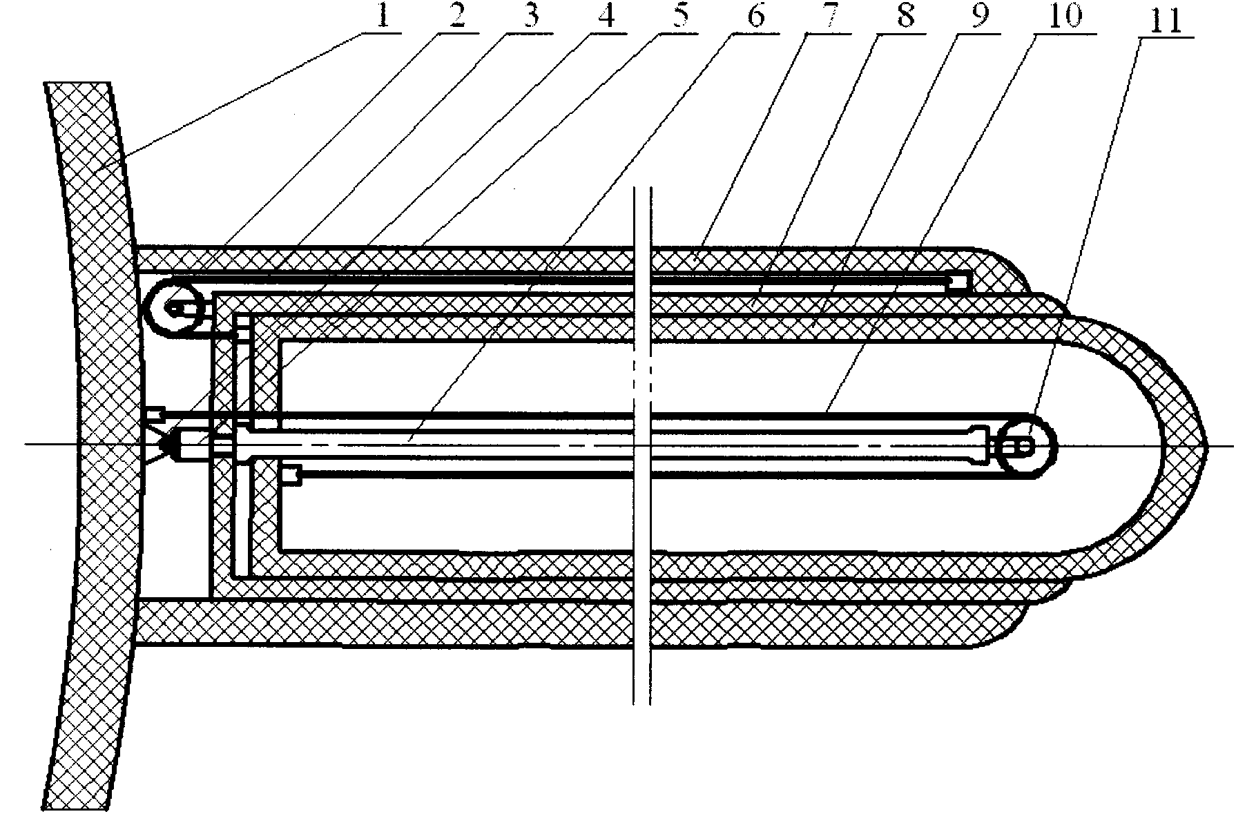
[0011] A telescopic wing is composed of wing I (7), wing II (8), wing III (9), pulley I (2), pulley II (11), steel cable I3), steel cable II (10), It consists of a hydraulic rod seat (4), a hydraulic rod (5), and a hydraulic cylinder (6). It is characterized in that: the wing I (7) is installed on the fuselage (1), the wing II (8) sliding sleeve is installed in the wing I (7), the wing III (9) sliding sleeve is installed in the wing II (8), The hydraulic rod seat (4) is fixed on the fuselage (1), one end of the hydraulic rod (5) is hinged on the hydraulic rod seat (4), and the other end is installed in cooperation with the hydraulic cylinder (6), and one end of the hydraulic cylinder (6) is fixed on the The pulley II (11) is installed on the wing II (8) and the other end, the pulley I (2) is fixed on the wing II (8), one end of the steel cable I (3) is fixed on the wing I (7), and the other end passes through The pulley I (2) is tightly fixed on the wing III (9), one end of t...


PUM


Abstract

The invention discloses a telescopic wing which consists of a wing I (7), a wing II (8), a wing III (9), a pulley I (2), a pulley II (11), a steel rope I (3), a steel rope II (10), a hydraulic rod seat (4), a hydraulic rod (5) and a hydraulic cylinder (6). The action of the wing is to generate lifting force so as to support airborne flight of an aircraft; the lifting force generated by the same wing is in a close relationship with the speed and height of the aircraft; for the same wing, when the height is the same, the higher the speed of the aircraft is, the higher the lifting force is; when the speed is the same, the larger the height is, the lower the lifting force is. According to the telescopic wing, when the aircraft carries out a cruising flight at a high altitude with thin air, the wing completely stretches out, only low fuel consumption is needed by the aircraft due to the ultra-wide wing, a low navigational speed is maintained, and the aim of prolonging the hang time can be achieved; moreover, the wing is completely shortened during sailing or course reversal, so that the flight speed is improved, and the sailing or course reversal time is shortened.

Description

technical field [0001] The invention relates to a wing, in particular to a retractable wing. Background technique [0002] With the needs of science and technology and military affairs, the flying altitude of high-altitude reconnaissance aircraft is getting higher and higher. For example, the cruising altitude of my country's "Xianglong" has reached 18,000 meters, and the cruising altitude of the American "Global Hawk" has reached 19,800 meters, exceeding the troposphere. 16,000 meters, reaching the height of the stratosphere. Since the higher the altitude, the thinner the air, in order to maintain sufficient lift, the aircraft flying at high altitudes with thin air must either increase the flight speed or widen the wingspan of the aircraft. Due to increasing the speed of flight, fuel consumption must be increased, and the time that the aircraft stays in the air is shortened. Therefore, in order to achieve the purpose of prolonging the time spent in the air, the wingspan of...

Claims


Application Information

Patent Timeline
Patent Type & Authority Applications(China)
IPC IPC(8): B64C3/54
Inventor 江村
Owner 枣庄铭世新型材料有限公司
Why Eureka
Try Eureka