[0025] Embodiments of the present invention will be described below with reference to the drawings. The present invention is not limited to the following embodiments, and various modifications and application examples of the technical concept of the present invention are also included in the scope of the present invention.
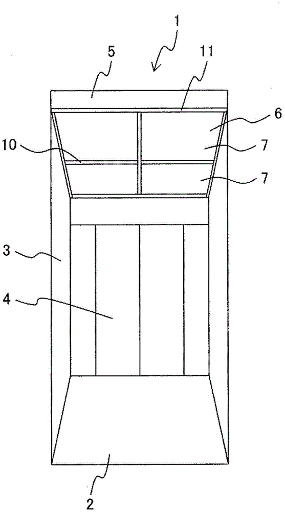
[0026] like figure 1 As shown, an elevator car 1 has a floor 2 , side panels 3 erected on the floor 2 , elevator doors 4 as entrances and exits, a ceiling 5 forming the top, and lighting devices 6 arranged on the ceiling 5 . The illuminating device 6 includes a milky-white light-transmitting plate 7 made of acrylic resin, and in this embodiment, the light-transmitting plate 7 is divided into four light-transmitting plates. The light-transmitting plate 7 is configured such that each outer peripheral edge thereof is supported by a cross-shaped center seam member 10 so as not to fall down.
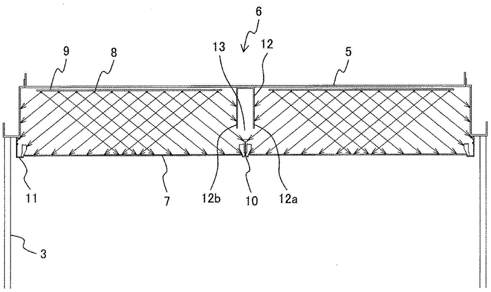
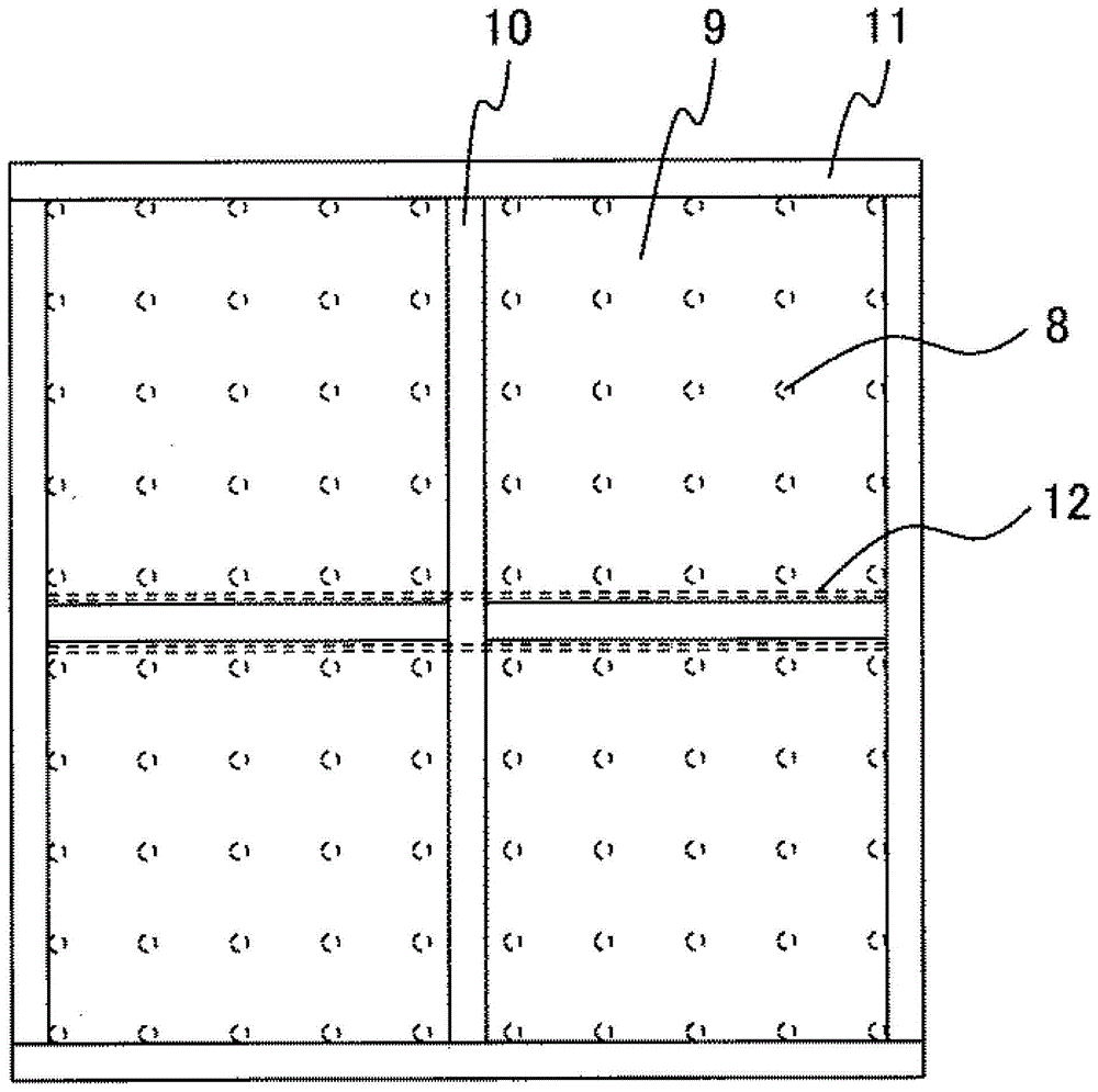
[0027] like figure 2 and image 3 As shown, the lighting device 6 has: a light-transmitting plate 7, which is arranged under the ceiling 5 and opposite to the ceiling 5, for example, is divided into four pieces; The LED lamp 8 between the light-transmitting plate 7 ; the central seam member 10 inserted into the divided part of the light-transmitting plate 7 ; and the peripheral seam member 11 provided around the light-transmitting plate 9 . The peripheral seam member 11 is fixed to the side panel 3 , and the central seam member 10 is configured to be fixed and supported by the peripheral seam member 11 . The central seam member 10 and the surrounding seam members 11 are made of aluminum, and its color is silver or milky white.
[0028] The size of the light-transmitting plate 7 is slightly larger than the rectangular opening size formed by the central seam member 10 and the surrounding seam members 11. The two sides of the light-transmitting plate 7 are placed on the central seam member 10 and the rest of the outer side The strip edges are supported so as to be placed on the surrounding seam member 11 .
[0029] In this embodiment, since the light-transmitting plate 7 is divided into four pieces, as image 3 As shown, the central seam member 10 is in the shape of a cross. The peripheral seam member 11 is used to support the two outer sides of the light-transmitting plate 7, so it will not be affected by shadows, and the central seam member 10 is set across the light-transmitting plate 7, so the central seam member 10 produces shadows.
[0030] figure 2 As shown, since the central seam member 10 is configured to support the light-transmitting plate 7 with its lower side portion, when the light of the LED lamp 8 is irradiated on the central seam member 10 protruding to the upper side of the light-transmitting plate 7, the A projected shadow of the central seam member 10 is produced in the direction of illumination. Therefore, the shadow is formed along the shape of the central seam member 10, and when the light-transmitting plate 7 is viewed from below, the dark area formed along the central seam member 10 can be seen. Therefore, this dark area has an unfavorable effect on aesthetics. It should be noted that, in this embodiment, the central seam member 10 is in the shape of a cross, and the same problem may occur in other shapes.
[0031] Also, in this embodiment, in order to prevent shadows from being generated near the center seam member 10, the following structure is employed. like figure 2 As shown, a light-shielding body 12 for shielding part of the light from the LED lamp 8 is provided on the ceiling 5 above the central joint member 10 , and a gap 13 is formed between the light-shielding body 12 and the central joint member 10 . The shade 12 has a U-shaped cross section, and its upper end surface is fixed to the ceiling 5 . The light-shielding body 12 also has two side end surfaces 12a, 12b vertically extending downward from both sides of the upper end surface.
[0032] That is, on the ceiling 5 located above the center seam member 10, a light shielding device is provided along the center seam member 10 to shield the light that forms the projected shadow of the center seam member 10 in the irradiation direction of the light of the LED lamp 8 . Body 12. By adopting this structure, the light of the LED lamp 8 that forms the projection shadow of the central seam member 10 in the irradiation direction toward the central seam member 10 can be shielded by the light shielding body 12, so in the irradiation direction of the LED lamp 8 It is difficult to form a cast shadow of the center seam member 10 .
[0033] In addition, the length of the gap 13 is set to be longer than the length that allows the translucent plate 7 to pass in the lateral direction, so that the LED lamp can be replaced by removing the translucent plate 7 when replacing the LED lamp.
[0034] like Figure 4 As shown, the length W between the side end surfaces 12a and 12b is set to be larger than the width of the central seam member 10 . In this way, by setting the length W between the side end surfaces 12a, 12b to be greater than the width of the central seam member 10, the light-shielding effect on the central seam member 10 can be improved, and the distance between the side end surfaces 12a, 12b of the light-shielding body 12 can be shortened. length. Thereby, a gap through which the light-transmitting plate 7 can pass can be formed. In this way, it also helps to shorten the overall length of the lighting device 6 in the thickness direction. It should be noted that if the length of the side end surfaces 12a, 12b of the light-shielding body 12 exceeds the necessary length, the projected shadow of the side end surfaces 12a, 12b may be projected onto the light-transmitting plate 7, so it is important to set it as Appropriate length.
[0035] Based on the above point of view, if Figure 4 As shown, the length W between the side end surfaces 12a, 12b of the light shielding body 12 is set to be greater than the width of the central seam member 10, and the length from the front end of the light shielding body 12 to the front end of the central seam member 10 is set to L is set to about 1/3 of the length from the ceiling 5 to the light-transmitting plate 7 .
[0036] The light-shielding body 12 is provided along the shape of the central seam member 10. In this embodiment, since the central seam member 10 is in the shape of a cross, the light-shielding body 12 is also formed in the shape of a cross. In addition, the surface of the light-shielding body 12 is formed in a color capable of absorbing light (for example, black). As the material of the black light-shielding body 12 , a black felt cut into thin strips and then electrostatically bonded can be used.
[0037] In the above description, if figure 2As shown, power is supplied from the power supply to the LED substrate 9, and each LED lamp 8 is illuminated by the power, and as shown in FIG. figure 2 Irradiate light as indicated by the arrow. The irradiation angle of the LED lamp 8 is set to 120°. In particular, part of the light irradiated from the LED lamp 8 disposed near the central joint member 10 is shielded by the two side end surfaces 12 a, 12 b vertically downward from the ceiling 5 side of the shade 12 . If the light is not blocked, the light will irradiate the central seam member 10 to form a projected shadow of the central seam member 10 in the irradiation direction. However, in this embodiment, since the light forming the projected shadow is shielded by the shade 12, it is possible to suppress the light from the LED lamp 8 from forming a shadow.
[0038] On the other hand, since the light irradiated on the central seam member 10 itself does not irradiate to the opposite side, no projected shadow is formed, and thus no darkness occurs.
[0039] In addition, when replacing the LED lamp 8, use a ladder to lift up the light-transmitting plate 7 where the LED lamp 8 to be replaced is located, and use the gap 13 formed between the light-shielding body 12 and the central seam member 10 , the light-transmitting plate 7 is moved sideways to form an opening, so that the LED lamp 8 can be replaced by using the opening.
[0040] As described above, according to the present invention, a light-shielding body that shields the light of the LED lamp that forms a projected shadow of the seam member is provided along the seam member on the ceiling located above the seam member, and the light-shielding body and the seam member space between. Therefore, since the light of the LED lamp that forms the projected shadow of the seam member is blocked by the shade, it is difficult to generate a projected shadow of the seam member in the irradiation direction of the LED lamp. As a result, a novel effect of improving the aesthetics of the light-transmitting plate can be obtained without producing a dark region along the joint member in the light-transmitting plate.
[0041] In addition, since the light-transmitting plate can pass through the gap between the joint member and the light-shielding body, the LED lamp can be replaced in the elevator car.