Heat recovery system

A heat recovery, hot water heat exchanger technology, applied in lighting and heating equipment, fluid circulation arrangements, refrigeration components, etc., can solve the problem of easy freezing and cracking of idle heat exchangers

Active Publication Date: 2014-06-11
GREE ELECTRIC APPLIANCES INC
View PDF11 Cites 6 Cited by
  • Summary
  • Abstract
  • Description
  • Claims
  • Application Information

AI Technical Summary

Problems solved by technology

[0006] The purpose of the present invention is to provide a heat recovery system to solve the technical problem that idle heat exchangers are prone to freezing and cracking

Method used


Image

  • Heat recovery system
  • Heat recovery system

Examples


Embodiment Construction

[0024] The embodiments of the present invention will be described in detail below with reference to the accompanying drawings, but the present invention can be implemented in many different ways defined and covered by the claims.

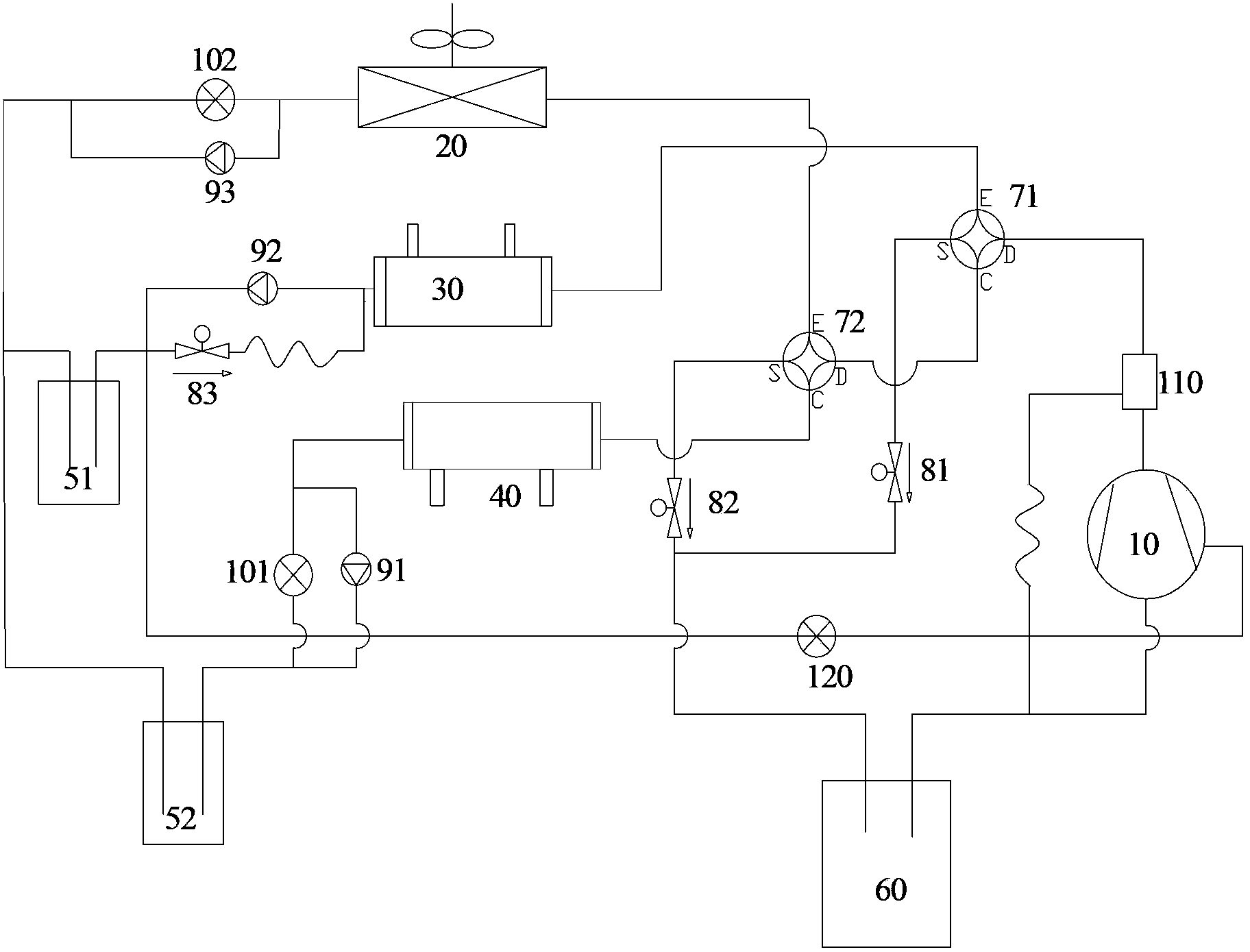
[0025] see figure 1 , the heat recovery system according to the present invention includes a compressor 10; a first liquid storage tank 51 and a second liquid storage tank 52; a first four-way valve 71 and a second four-way valve 72; an outdoor heat exchanger 20, the outdoor heat exchanger The inlet end of the heat exchanger 20 is connected with the first valve port of the second four-way valve 72, and the outlet end of the outdoor heat exchanger 20 is connected with the first liquid storage tank 51 and the second liquid storage tank 52; 30, the inlet end of the hot water heat exchanger 30 communicates with the first valve port of the first four-way valve 71, and the outlet end of the hot water heat exchanger 30 communicates with the first liquid st...


PUM


Abstract

The invention discloses a heat recovery system. The heat recovery system comprises a compressor, a first liquid storage tank, a second liquid storage tank, a first four-way valve, a second four-way valve, an outdoor heat exchanger, a hot water heat exchanger and an indoor heat exchanger, wherein the first four-way valve is connected with the second four-way valve, the inlet end of the outdoor heat exchanger is connected with a first valve port of the second four-way valve, the outlet end of the outdoor heat exchanger is connected with the first and second liquid storage tanks, the outlet end of the hot water heat exchanger is connected with a first valve port of the first four-way valve, the outlet end of the hot water heat exchanger is connected with the first liquid storage tank, the inlet end of the indoor heat exchanger is connected with a third valve port of the second four-way valve, the outlet end of the indoor heat exchanger is connected with the second liquid storage tank, a first electromagnetic valve is mounted between the inlet end of a compressor and a second valve port of the first four-way valve, and a second electromagnetic valve is mounted between the inlet end of the compressor and a second valve port of the second four-way valve. The heat recovery system solves the anti-freezing problem for an idle heat exchanger.

Description

technical field [0001] The invention relates to the field of heat recovery, in particular to a heat recovery system. Background technique [0002] The heat recovery system design in the prior art has the following problems: [0003] Putting the idle heat exchanger on the high-pressure side can solve the anti-freezing problem of the heat exchanger, but the hot water mode cannot defrost directly, so it needs to be solved by switching the mode; put the idle heat exchanger on the low-pressure side, the hot water mode can not be switched Mode defrost directly, but the antifreeze of the heat exchanger cannot be guaranteed. [0004] In the solutions in the prior art, either heating water cannot defrost and can only be converted to heating defrosting, or heating water defrosting cannot be implemented and can only be realized by switching to heating mode. [0005] In other solutions, when heating or hot water, the idle heat exchanger will be on the low pressure side, and the refrig...

Claims


Application Information

Patent Timeline
Patent Type & Authority Applications(China)
IPC IPC(8): F25B41/04F25B41/20
Inventor 卓明胜陈忠杰廖荣张龙爱位静王国栋
Owner GREE ELECTRIC APPLIANCES INC
Why Eureka
Try Eureka