Angle position test tool of clock spring installation board and ignition switch installation frame

An ignition switch, clock spring technology, applied in measuring devices, angle/taper measurement, instruments, etc., can solve the problems of large detection error, small detection error, high detection efficiency, and achieve simple and practical structure, small detection error, and detection efficiency. high effect

Inactive Publication Date: 2014-06-11
ZHEJIANG GEELY HLDG GRP CO LTD +1
View PDF5 Cites 7 Cited by
  • Summary
  • Abstract
  • Description
  • Claims
  • Application Information

AI Technical Summary

Problems solved by technology

[0003] The purpose of the present invention is in order to overcome the relative angular position of the location square hole of three installation holes of spline section, clock spring mounting plate and ignition switch installation frame and the quality of spline section respectively with traditional measuring tool at present, there is detection error big and Insufficient detection efficiency is low, providing a method for detecting the relative angular position of the spline segment, the three mounting holes of the clock spring mounting plate and the positioning square hole of the ignition switch mounting frame and the quality of the spline segment, with small detection error and high detection efficiency Clock spring mounting plate position checker

Method used


Image

  • Angle position test tool of clock spring installation board and ignition switch installation frame
  • Angle position test tool of clock spring installation board and ignition switch installation frame
  • Angle position test tool of clock spring installation board and ignition switch installation frame

Examples


Embodiment Construction

[0018] The present invention will be further described below in conjunction with the accompanying drawings.

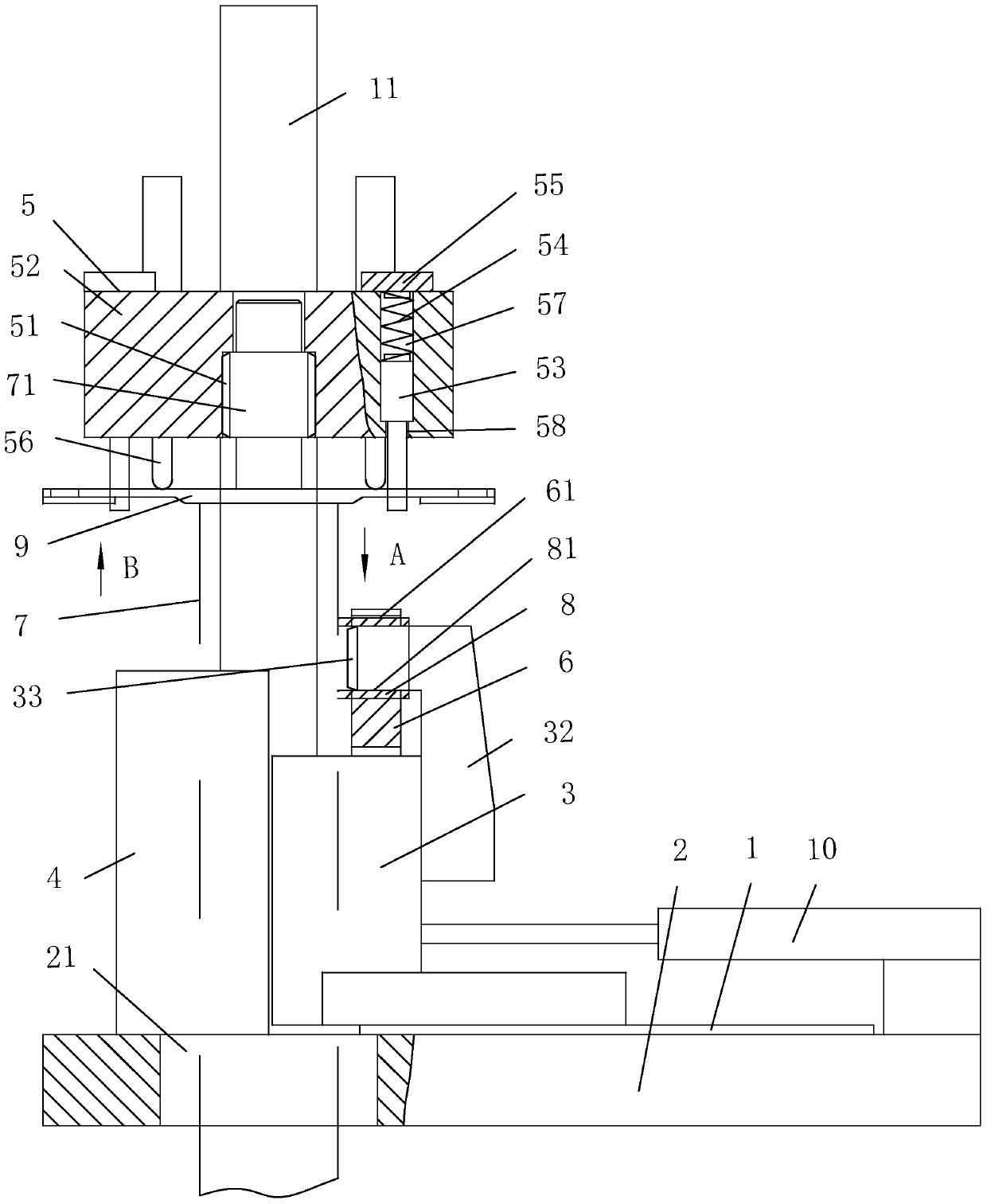
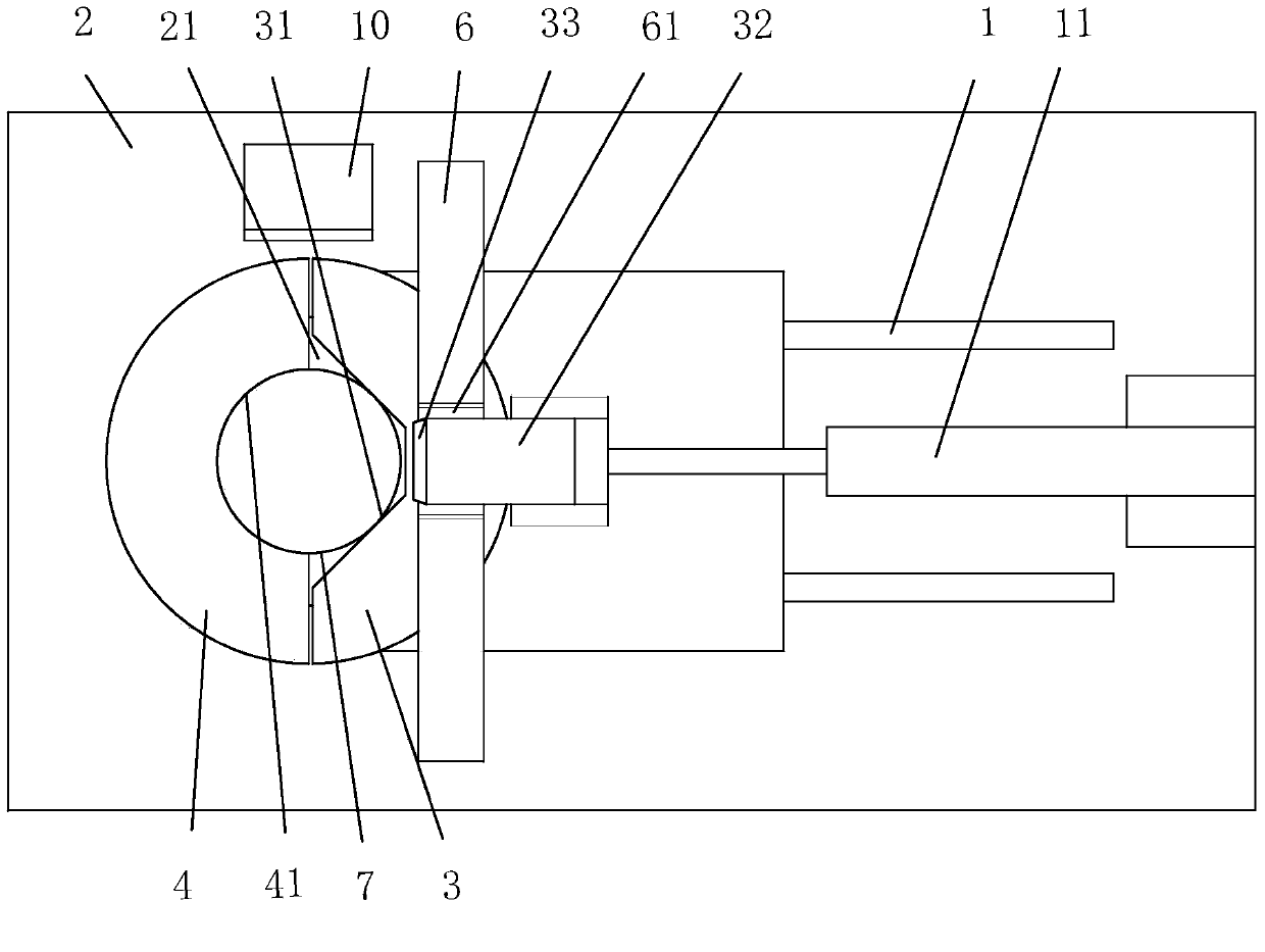
[0019] as attached figure 1 , attached figure 2 , attached image 3 , attached Figure 4 Shown: a clock spring mounting plate and an ignition switch mounting frame angle position checker, including the base plate 2 and the right clamping block 3 connected with the base plate 2 through the slide rail 1 and having the right clamping groove 31 and the square hole positioning head 32, the right Clamp driving device 10, left clamp block 4 with left clamp groove 41 and screw connection with bottom plate 2 and lifting device 11, spline section connected with lifting device 11 and mounting hole detection assembly 5, with width and ignition switch mounting frame The positioning groove 61 that the width clearance of 8 fits and the positioning block 6 that is connected with the bottom plate 2 screws.

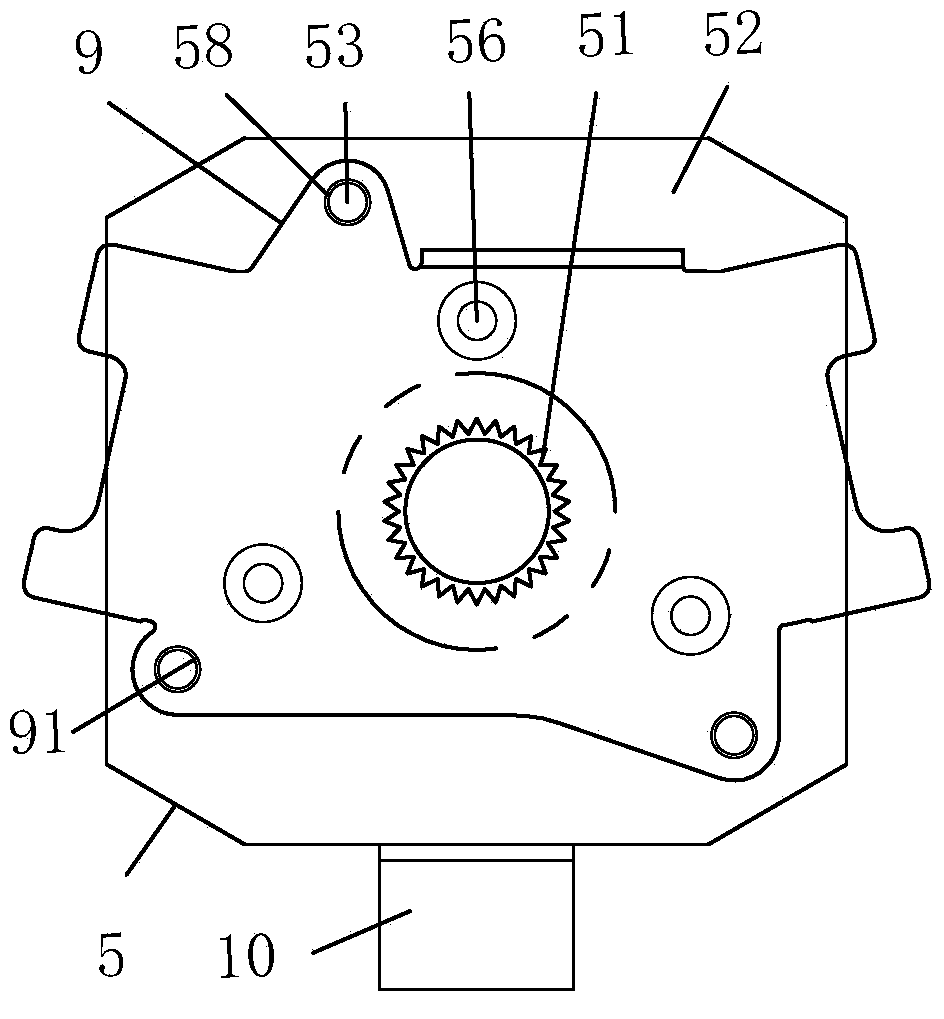
[0020] The spline segment and mounting hole detection assembly 5 includes...


PUM


Abstract

The invention relates to the field of automobile part detection devices, and provides an angle position test tool of a clock spring installation board 9 and an ignition switch installation frame 8. The angle position test tool of the clock spring installation board and the ignition switch installation frame comprises a bottom board, a right clamping block, a right clamping block drive device, a left clamping block, a lifting device, a spline section and installation hole detection assembly, a locating groove and a locating block, wherein the right clamping block is connected with the bottom board through a slide way and is provided with a right clamping groove and a square hole locating head; the left clamping block is provided with a left clamping groove and is fixedly connected with the bottom board; the spline section and installation hole detection assembly is connected with the lifting device; the locating groove is matched with the ignition switch installation frame in width; the locating block is fixedly connected with the bottom board. The angle position test tool of the clock spring installation board and the ignition switch installation frame is small in detection error and high in detection efficiency.

Description

technical field [0001] The invention relates to the field of detection devices for other parts of automobiles, in particular to a detection tool for the angular position of a clock spring mounting plate and an ignition switch mounting frame. Background technique [0002] The invention of Chinese patent application number CN201010257429.0 discloses a new type of clock spring, which includes an upper housing and a lower housing. A sliding plate made of conductive material is fixedly connected to the housing, and the sliding plate is connected to the vehicle power supply. A thimble assembly is connected to the upper housing, and the thimble in the thimble assembly is always in contact with the sliding plate. The thimble in the thimble assembly is made of conductive material. Made and the thimble is connected with the electrical appliances at the steering wheel. The upper case and the lower case of the clock spring of the automobile are fixedly connected to the steering wheel f...

Claims


Application Information

Patent Timeline
Patent Type & Authority Applications(China)
IPC IPC(8): G01B5/24G01B21/22
Inventor 叶钦鸿潘巨林
Owner ZHEJIANG GEELY HLDG GRP CO LTD
Why Eureka
Try Eureka