Switching power conversion circuit and its applicable power supply

A power conversion circuit and power circuit technology, which are used in high-efficiency power electronic conversion, output power conversion devices, and irreversible AC power input conversion into DC power output, etc. characteristics, high power consumption of the circuit, etc.

Active Publication Date: 2017-02-08
DELTA ELECTRONICS (SHANGHAI) CO LTD
View PDF11 Cites 0 Cited by
  • Summary
  • Abstract
  • Description
  • Claims
  • Application Information

AI Technical Summary

Problems solved by technology

[0005] Although the switching power conversion circuit has high conversion efficiency, the switching power conversion circuit will continue to operate regardless of whether the traditional switching power conversion circuit needs to provide power to the load or electronic products, so that the output voltage maintains the rated voltage. Voltage value
Therefore, even if the switching power conversion circuit does not need to provide power to the load or electronic products, the switching power conversion circuit will continue to operate and consume power, causing the switching power conversion circuit to have a function when it does not need to provide power to the load or electronic products higher power consumption
[0006] It can be seen from the above that when the load or electronic product does not need to use the electric energy provided by the switching power conversion circuit, for example, when the load or electronic product stops operating, the traditional switching power conversion circuit will continue to operate. As a result, the overall circuit has high power consumption, which does not meet the characteristics of energy saving and power saving
If a power supply using a traditional switching power conversion circuit provides power to electronic products, even if the user is not using the electronic product, the power supply will continue to operate and consume unnecessary power

Method used


Image

  • Switching power conversion circuit and its applicable power supply
  • Switching power conversion circuit and its applicable power supply
  • Switching power conversion circuit and its applicable power supply

Examples


Embodiment Construction

[0088] Some typical embodiments embodying the features and advantages of the present invention will be described in detail in the description in the following paragraphs. It should be understood that the present invention can be changed in various ways without departing from the scope of the present invention, and that the description and illustrations therein are illustrative in nature rather than limiting the present invention.

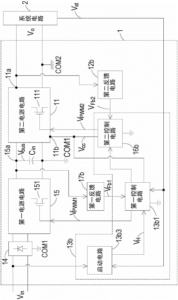
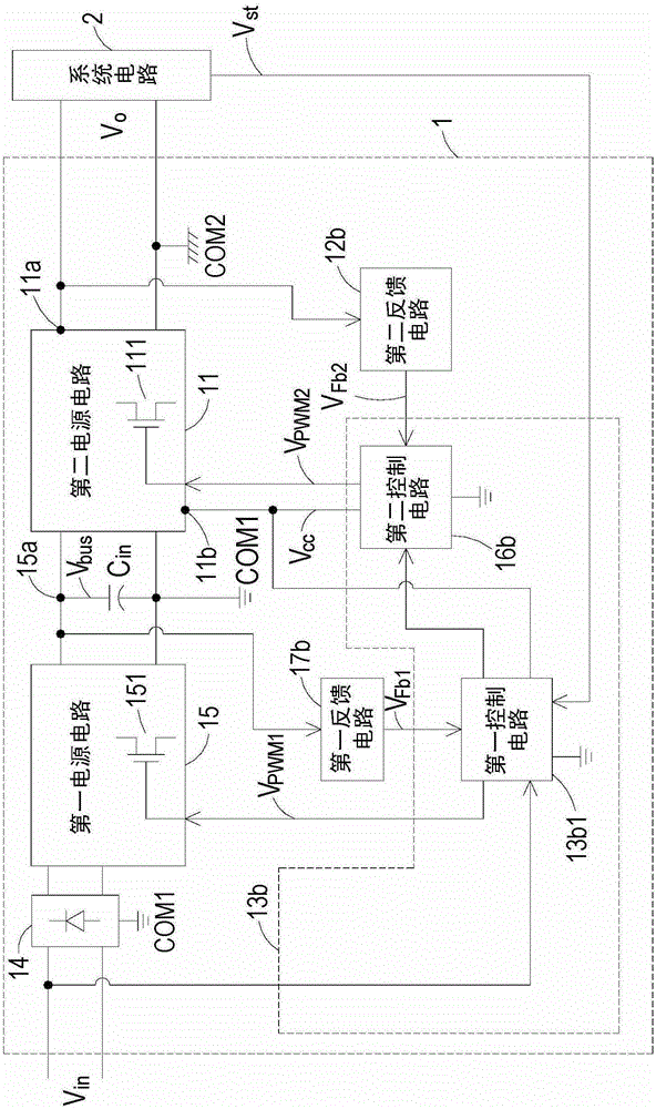
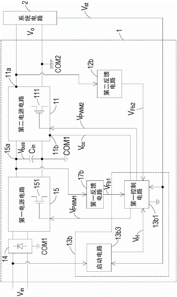
[0089] see figure 1 , which is a circuit block diagram of a switching power conversion circuit in a preferred embodiment of the present invention. Such as figure 1 As shown, the switching power supply conversion circuit 1 of the present invention is used to receive the input voltage V in , such as an AC voltage of electrical energy, output a rated output voltage V o , and can be but not limited to a dual-stage circuit structure including a first power supply circuit 15 and a second power supply circuit 11, and can be applied in a power supply to ...


PUM


Abstract

PROBLEM TO BE SOLVED: To provide a switching power conversion circuit that has a power-factor improvement function by having a two-stage circuit configuration.SOLUTION: A switching power conversion circuit of the present invention includes: a first power circuit for correcting a power factor and converting an input voltage into a bus voltage; a first feedback circuit connected to the first power circuit for outputting a first feedback signal according to the bus voltage; a second power circuit connected to the first power circuit for converting the bus voltage into an output voltage; a second feedback circuit connected to the second power circuit for outputting a second feedback signal according to the output voltage; and a controlling unit connected to the first power circuit, the second power circuit, the first feedback circuit, the second feedback circuit, and a system circuit for controlling the operation of the first power circuit according to the first feedback signal, controlling the operation of the second power circuit according to the second feedback signal, and receiving a power-supply status signal of the system circuit.

Description

technical field [0001] The present invention relates to a power conversion circuit, in particular to a switching power conversion circuit with a two-stage circuit structure and an applicable power supply. Background technique [0002] In recent years, with the advancement of science and technology, electronic products with various functions have been gradually developed. These electronic products with various functions not only meet the various needs of people, but also integrate into everyone's needs. Daily life makes people's life more convenient. [0003] These various electronic products with different functions are composed of various electronic components, and the power supply voltage required by each electronic component is different. Therefore, the AC power provided by today's power supply system is not suitable for directly supplying electronic products use. In order to provide an appropriate voltage for each electronic component to operate normally, these electro...

Claims


Application Information

Patent Timeline
Patent Type & Authority Patents(China)
IPC IPC(8): H02M7/12H02M1/36H02M3/156
CPCY02B70/10
Inventor 魏冬焦德智蒋进财
Owner DELTA ELECTRONICS (SHANGHAI) CO LTD
Why Eureka
Try Eureka