
A method and device for automatic switching of ECG-driven leads

An automatic switching and lead technology, which is applied in medical science, sensors, diagnostic recording/measurement, etc., can solve problems such as inconvenient use, reduced measurement efficiency, and falling off

Active Publication Date: 2015-10-14
EDAN INSTR
View PDF6 Cites 0 Cited by
  • Summary
  • Abstract
  • Description
  • Claims
  • Application Information

AI Technical Summary

Problems solved by technology

[0005] During use, due to the movement of the patient or other collisions or damage to the lead wires, the lead wires will fall off or have poor contact, and the non-driven leads will fall off or damaged, the ECG signal related to the lead line cannot be measured, but the ECG signal not related to the lead line can still be measured, and it does not affect the use when displaying multiple waveforms; while the driving lead falls off Or when the contact is poor, it may cause the ECG signal to be undetectable or the quality of the ECG signal is poor. The existing technology can judge that the lead is off, and whether the corresponding bioelectrical signal is received. If not, or the signal is abnormal, it is judged as a lead Leads (including drive leads) fall off
However, when the driving lead falls off or is in bad contact, only a corresponding alarm is issued, and the user must reconnect or replace the driving lead wire to continue to use, which is time-consuming, inconvenient to use, and reduces measurement efficiency

Method used

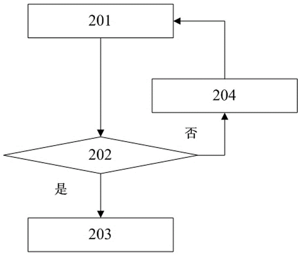
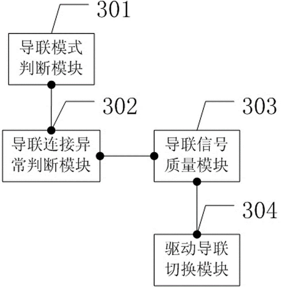

Image

  • A method and device for automatic switching of ECG-driven leads
  • A method and device for automatic switching of ECG-driven leads
  • A method and device for automatic switching of ECG-driven leads

Examples


Embodiment Construction

[0038] In order to make the object, technical solution and advantages of the present invention clearer, the present invention will be further described in detail below in conjunction with the accompanying drawings and embodiments. It should be understood that the specific embodiments described here are only used to explain the present invention, not to limit the present invention.

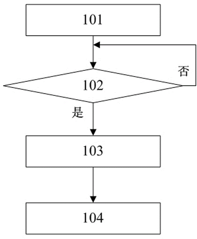
[0039] A flow chart of an embodiment of the method for automatic switching of electrocardiographically driven leads in the present invention, please refer to figure 1 :

[0040] 101. Judging the current ECG lead working mode;

[0041] The medical monitoring system is turned on and judges the current working mode of ECG lead monitoring according to the preset relevant information or user trigger setting information or the number of lead wires connected. The general lead modes include: 12-lead mode, 5-lead mode mode and 3-lead mode;

[0042] 102. If it is judged as a 12-lead mode or a 5-lea...


PUM


Abstract

The invention relates to the field of medical electrocardio signal guarding, in particular to an electrocardio driving lead automatic switching method and an electrocardio driving lead automatic switching device. The driving lead automatic switching technology is used for avoiding the problem that an electrocardio signal can not be measured due to abnormal connecting conditions that a driving lead wire drops or is not connected well and the like. A user can continue to measure the electrocardio signal without manually reconnecting the driving lead wire or changing the driving lead wire. The electrocardio driving lead automatic switching device is time-saving, convenient and better in user experience.

Description

technical field [0001] The invention relates to the field of medical electrocardiographic signal monitoring, in particular to a method and a device for automatically switching electrocardiographically driven leads. Background technique [0002] The electrocardiogram (ECG for short) signal is the reflection of the electrical activity of the heart over a period of time. It is collected by skin electrodes, and then the skin electrodes are connected with the ECG lead wires to transmit the ECG signals to the ECG measurement circuit. Skin electrodes are generally placed on various parts such as limbs and chest. [0003] In ECG monitoring, three modes of 3-lead, 5-lead and 12-lead are mainly used. Among them, the 3-lead mode uses three lead wires of the right arm (RA), left arm (LA), and left leg (LL), and can display three waveforms of I, II, and III. Since in the 3-lead mode, there are only three lead wires, and the ECG signal is a differential signal, each waveform is obtained...

Claims


Application Information

Patent Timeline
Patent Type & Authority Patents(China)
IPC IPC(8): A61B5/0402
Inventor 岳青秦钊
Owner EDAN INSTR
Learn More