
Electric tool

A technology of electric tools and tool magazines, applied in the field of tools, can solve the problems of large volume, energy consumption, and complex structure of electric tools, and achieve the effect of simple structure and long service life

Inactive Publication Date: 2014-06-18
NINGBO HAILIAN ELECTRIC APPLIANCE
View PDF5 Cites 4 Cited by
  • Summary
  • Abstract
  • Description
  • Claims
  • Application Information

AI Technical Summary

Problems solved by technology

[0002] At present, there is an electric tool, which includes a motor, a gearbox, a push rod for storing and storing tools, a tool magazine, and a tool holder. The motor is connected to the input of the gearbox, and the output of the gearbox is connected to the push rod. After one end enters the tool holder, the push rod drives the tool holder to rotate, or the output part of the gearbox is connected to the tool holder, and the output part drives the tool holder to rotate, but no matter what it is, the first gear is generally set on the output part, The push rod or the tool holder is provided with a second gear, and the first gear meshes with the second gear to realize the connection, which makes the output member and the tool holder not located on the same axis. At the same time, the arrangement of the push rod requires space, resulting in power tools The circumferential volume is large, the structure is complex, and it is not compact enough; in order to be able to push the tool into the tool holder, the push rod can move axially, and there are two positions, one position, the retraction of the push rod will be located in the tool holder The tool is brought back to the tool magazine for storage. At this time, the tool magazine can be rotated. The user rotates the tool magazine to select a tool. After selection, the push rod extends forward to push the tool into the tool holder. The axial movement structure of the rod is designed, so the structure is relatively complicated. At the same time, when the tool chuck rotates, the push rod also needs to rotate, which consumes more energy. The other end of the push rod is generally connected to a push-pull seat, and the push rod needs to be able to rotate relative to the push-pull seat. In this way, the other end of the push rod and the push-pull seat will be worn and damaged due to relative rotation, which is not conducive to improving the service life of the electric tool

Method used


Image

  • Electric tool
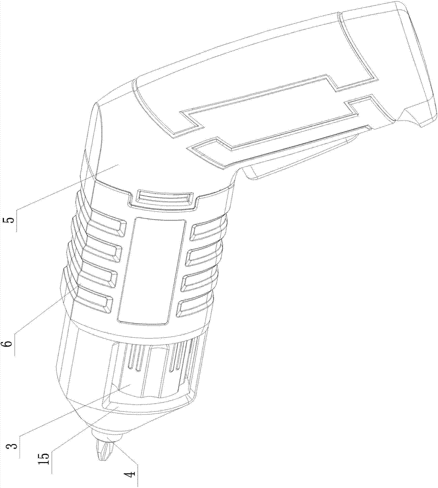
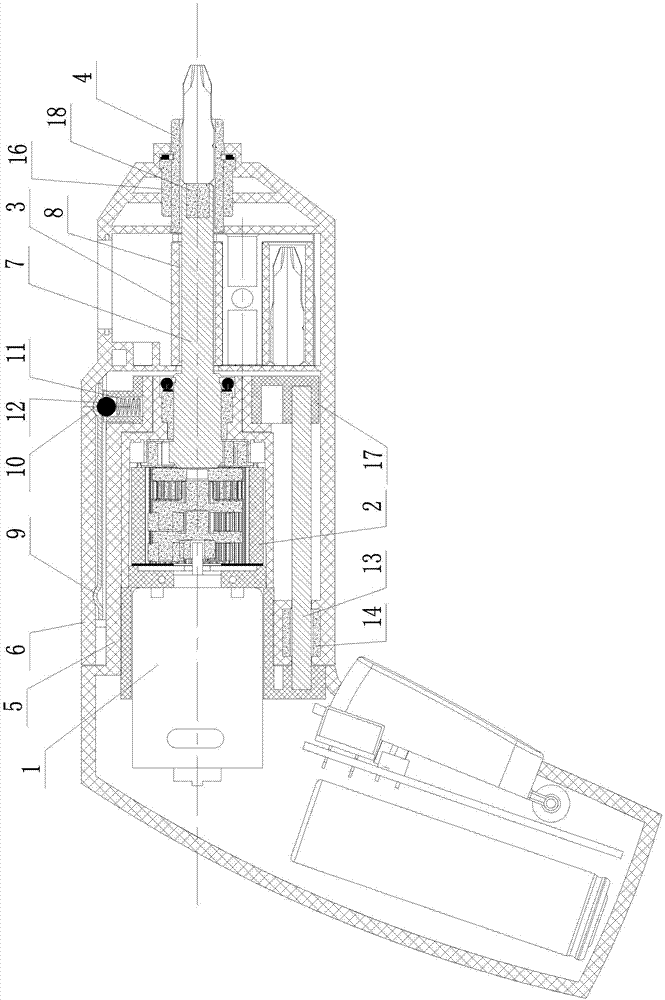
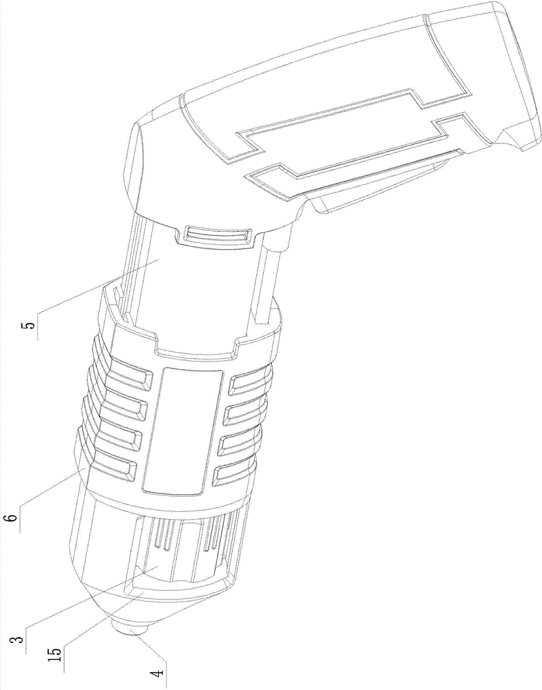
  • Electric tool
  • Electric tool

Examples


Embodiment Construction

[0021] Below in conjunction with accompanying drawing and specific embodiment the present invention will be described in further detail:

[0022] The electric tool of the present invention includes a motor 1, a gearbox 2, a tool magazine 3, and a tool holder 4. The motor 1 is connected to the input part of the gearbox 2, and it also includes a first housing (5) and a second housing ( 6), the motor (1) and the gearbox (2) are arranged in the first housing (5), the tool magazine (3) and the tool holder (4) are arranged in the second housing (6), and the tool magazine ( 3), the tool holder (4) and the second housing (6) can be relatively rotatably connected, and the first housing (5) and the second housing (6) can move relatively axially so that the gearbox (2) The output part (7) of the tool magazine (3) and one of the tool holes (8) and the tool holder (4) are sequentially socketed or separated in the opposite direction, and the output part (7) is connected to the tool holder (...


PUM


Abstract

The invention provides an electric tool which has the advantages of simple and compact structure, energy saving and long service life. The electric tool comprises a motor (1), a gearbox (2), a tool magazine (3) and a tool chuck (4), wherein the motor (1) is connected with an input part of the gearbox (2), the motor (1) and the gearbox (2) are arranged in a first shell (5), the tool magazine (3) and the tool chuck (4) are arranged in a second shell (6), the first shell (5) and the second shell (6) can relatively and axially move to enable an output part (7) of the gearbox (2) to be sequentially sheathed with or reversely separated from one tool hole (8) of the tool magazine (3) and the tool chuck (4), the output part (7) is circumferentially sheathed with the tool chuck (4) in a driving way, and the second shell (6) is provided with a structure for driving the tool magazine (3) by a user; the output part (7), the tool hole (8) and the tool chuck (4) are arranged on the same axis.

Description

technical field [0001] The invention relates to a tool, specifically an electric tool. Background technique [0002] At present, there is an electric tool, which includes a motor, a gearbox, a push rod for storing and storing tools, a tool magazine, and a tool holder. The motor is connected to the input of the gearbox, and the output of the gearbox is connected to the push rod. After one end enters the tool holder, the push rod drives the tool holder to rotate, or the output part of the gearbox is connected to the tool holder, and the output part drives the tool holder to rotate, but no matter what it is, the first gear is generally set on the output part, The push rod or the tool holder is provided with a second gear, and the first gear meshes with the second gear to realize the connection, which makes the output member and the tool holder not located on the same axis. At the same time, the arrangement of the push rod requires space, resulting in power tools The circumfere...

Claims


Application Information

Patent Timeline
IPC IPC(8): B25D11/00B25D11/06B25D17/00B25D17/08B25F5/02
Inventor 黄永林何岳存
Owner NINGBO HAILIAN ELECTRIC APPLIANCE
Learn More